Cleaning unit and image forming apparatus

A technology for cleaning units and imaging equipment, applied in the direction of equipment, electrographics, optics, etc. using electric recording technology of charge patterns, to achieve the effects of long service life, suppression of damage, and improvement of cleaning performance

Inactive Publication Date: 2009-03-18
FUJIFILM BUSINESS INNOVATION CORP
View PDF11 Cites 0 Cited by
  • Summary
  • Abstract
  • Description
  • Claims
  • Application Information

AI Technical Summary

Problems solved by technology

[0017] The technique disclosed in Japanese Patent Application Laid-Open No. 2002-244522 relates to a technique aimed at scraping off discharge products with a fiber body by wiping the photoreceptor surface with the fiber body on the upstream side with respect to the photoreceptor rotation direction of the brush, and for Residual toner particles adjusted to one polarity by techniques disclosed in JP-A-63-15278, JP-A-2004-239999, JP-A-2001-109351 and JP-A-2001-3413 , when they pass through the fibrous body, they become charged with opposite polarity due to triboelectric charging, so there is a fear that the residual toner particles cannot be removed by the brush

Method used


Image

  • Cleaning unit and image forming apparatus
  • Cleaning unit and image forming apparatus
  • Cleaning unit and image forming apparatus

Examples


Embodiment 1

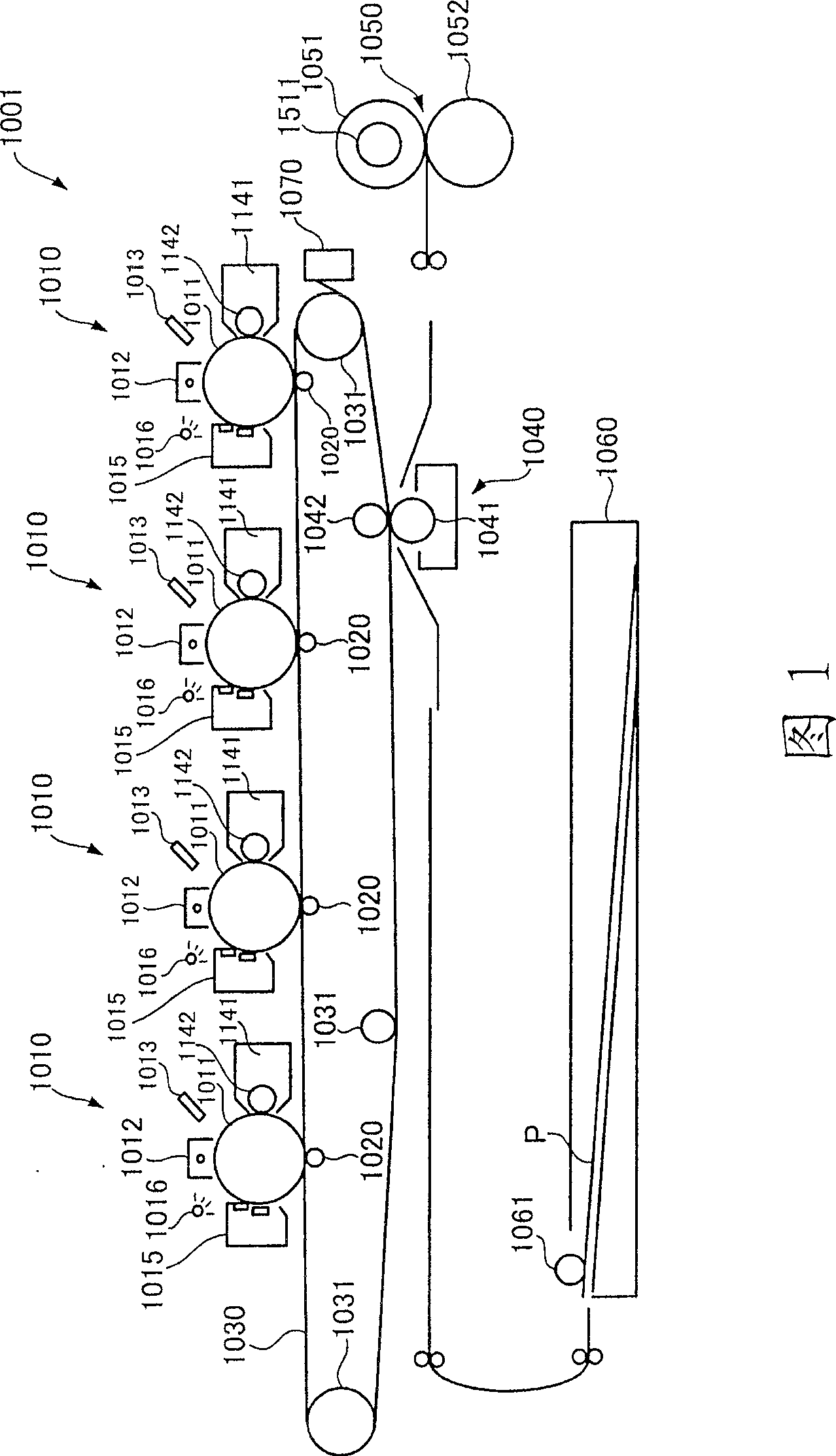
[0263] As a test machine, a modified Fuji Xerox Co., Ltd. Docu-Center Color 500 was used. That is, a photoreceptor A having a protective layer formed on its surface was assembled as a photoreceptor. Assemble the cleaning unit equipped with cleaning blade A and cleaning accessory A. Durability of about 100,000 images was performed at low temperature / low humidity (10°C, 20% relative humidity) and high temperature / high humidity (28°C, 80% relative humidity) using a product developer of Docu-Center Color500 as the developer A resistance test to evaluate wear of the photoreceptor and scratches on the photoreceptor (photoreceptor roughness). In addition, the occurrence of filming at low temperature / low humidity was evaluated, and the image flow at high temperature / high humidity was evaluated. These results are presented in Table 2 together with a comprehensive assessment.

[0264] Table 2

[0265]

[0266] The details of each assessment are as follows.

[0267]...

Embodiment 2~5

[0290] The same tests and evaluations as in Example 1 were performed using the same image forming apparatus as in Example 1 except that the cleaning blade was changed to that shown in Table 2. The results are shown in Table 2.

Embodiment 6~8

[0292] The same tests and evaluations as in Example 1 were performed using the same image forming apparatus as in Example 1 or 2 except that the cleaning blade was changed to that shown in Table 2. The results are shown in Table 2.


PUM


Abstract

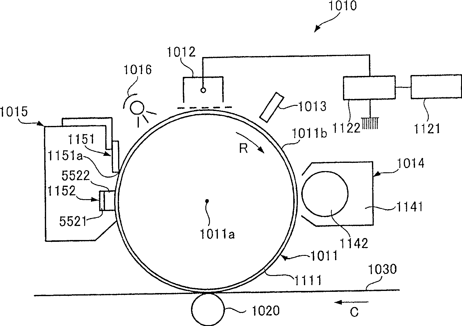
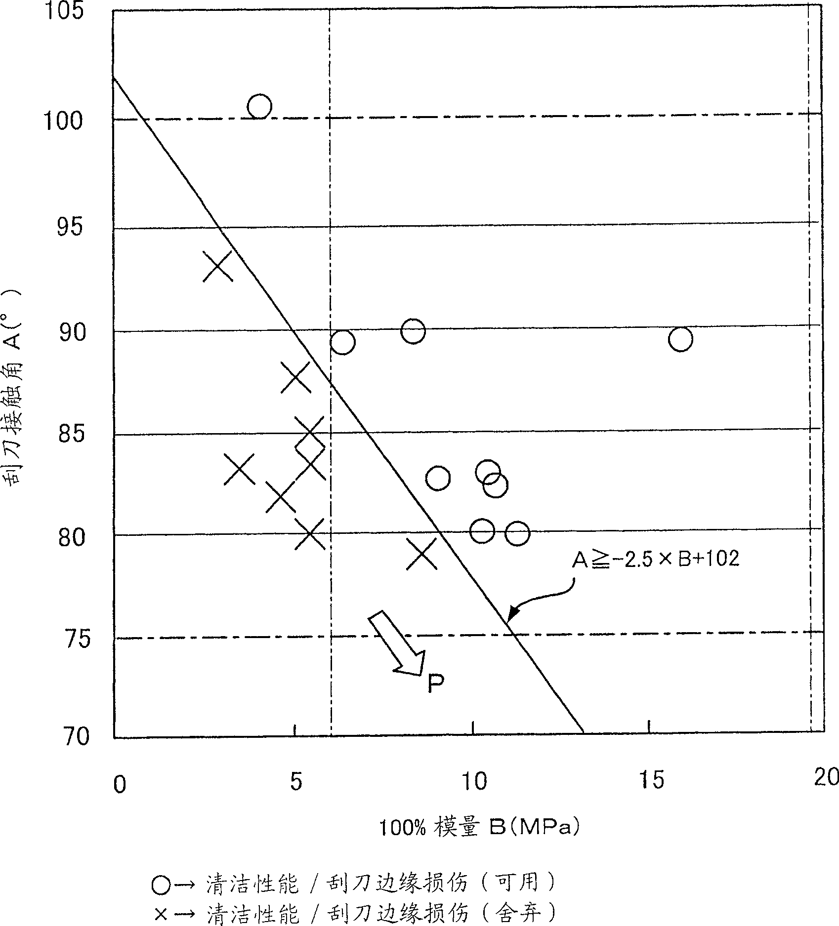
This invention relates to a cleaning unit comprising: a cleaning blade that keeps a front end of rubber material in contact with the surface with a pressure so as to scrape residual toner left on the surface of the photoreceptor and a fiber body having multiple fibers in contact with the surface of the photoreceptor in the upstream in the cyclic moving direction of the surface of the photoreceptor with respect to the cleaning blade, wherein the cleaning blade satisfies conditions A>=-2.5xB+102 and 6.3<=B<=19.6, where A designates a contact angle ( DEG ) with pure water under 23 DEG C, 55% RH and B designates 100% modulus (MPa) at 23 DEG C.

Description

technical field [0001] The present invention relates to a cleaning unit for removing residues such as residual toner used in an electrophotographic system including a copying machine, a facsimile machine, and a printer, and an image forming apparatus equipped with the cleaning unit. Background technique [0002] According to the conventional electrophotographic method, in the toner image forming cycle, the surface of the photoreceptor undergoing cyclical movement such as rotation around a central axis in a predetermined direction is charged with a charger, and the surface of the photoreceptor after being charged is irradiated with an exposure light source. An electrostatic latent image is formed on the surface of the photoreceptor, and then the electrostatic latent image is developed by a developer to form a toner image on the surface of the photoreceptor, and the toner image formed on the surface of the photoreceptor is transferred to a predetermined The surface of the tran...

Claims


Application Information

Patent Timeline
Patent Type & Authority Patents(China)
IPC IPC(8): G03G21/10G03G15/00
Inventor 重崎聪奥山浩江坂廼邉真新宅宽治杉浦聪哉曾我达也岩崎仁黑田能孝
Owner FUJIFILM BUSINESS INNOVATION CORP
Why Eureka
Try Eureka