
Optical transceiver module

A technology of optical transceiver and optical receiving module, which is applied in the direction of lasers, phonon exciters, laser components, etc., can solve the problems of inability to suppress electrical interference, achieve enhanced GND potential stability, suppress potential fluctuations, and suppress electrical crosstalk Effect

Inactive Publication Date: 2009-01-28
FUJITSU LTD
View PDF4 Cites 0 Cited by
  • Summary
  • Abstract
  • Description
  • Claims
  • Application Information

AI Technical Summary

Problems solved by technology

However, this technique cannot suppress electrical interference occurring between the transmitting and receiving parts of the optical receiver module in which the LD module 100, PD module 200, and circuit board 300 are integrated.

Method used


Image

  • Optical transceiver module
  • Optical transceiver module
  • Optical transceiver module

Examples


Embodiment Construction

[0040] [A] Description of the first embodiment

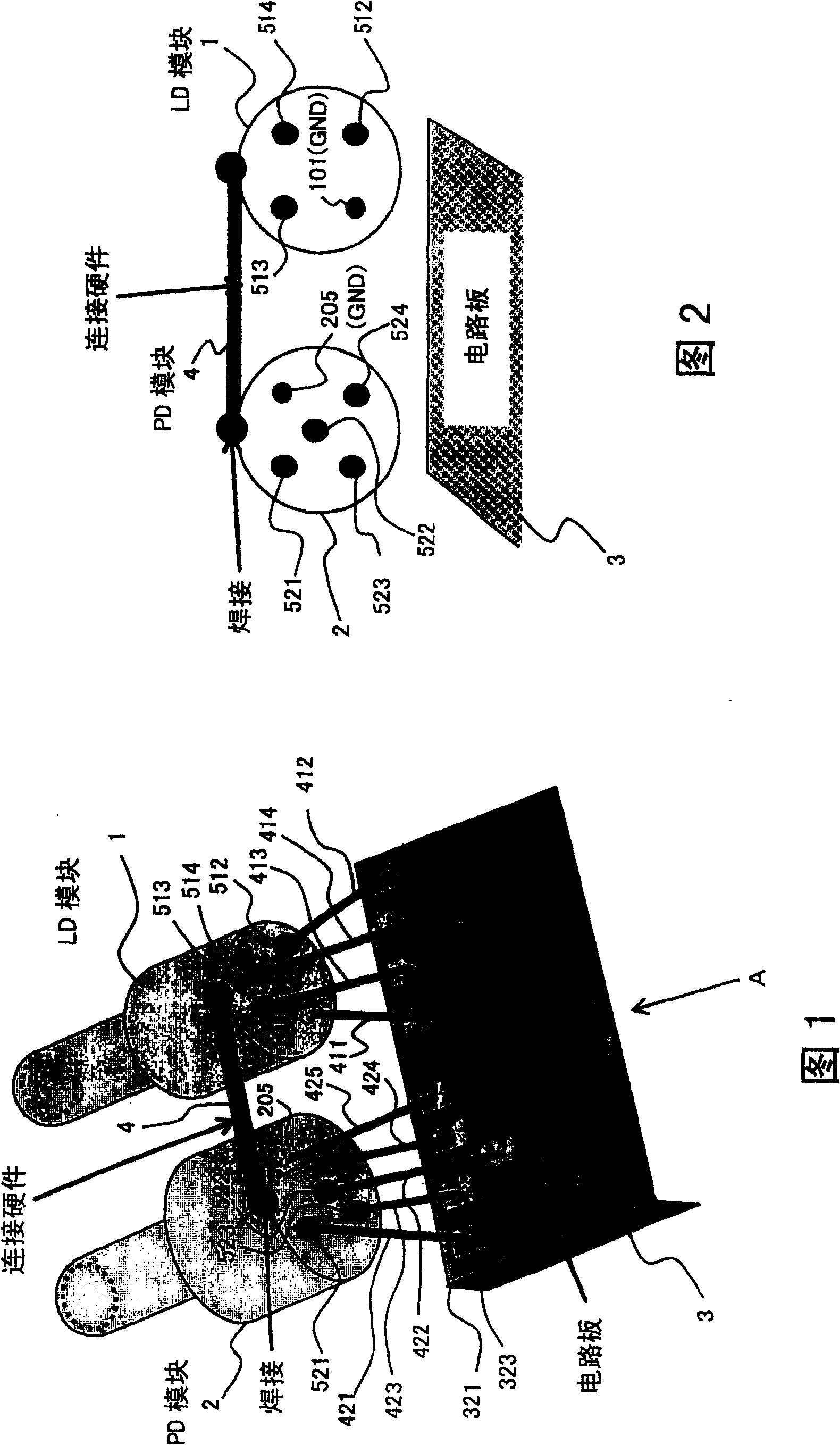
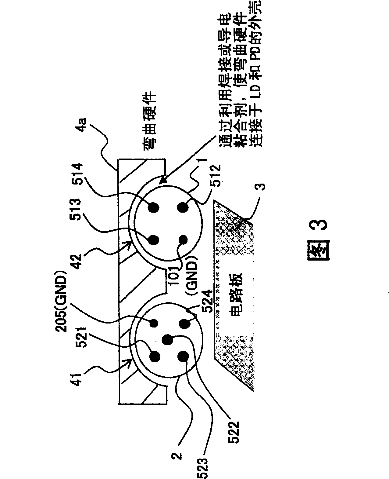
[0041] FIG. 1 is a diagrammatic perspective view showing the structure of an optical transceiver module as a first embodiment of the present invention. FIG. 2 is a diagrammatic front view of the optical transceiver module when viewed in the direction of arrow A given in FIG. 1 . As shown in Fig. 1 and Fig. 2, the optical transceiver module of the present invention comprises: CAN type LD module 1, and it has the LD (light emitting element) that is positioned at the cylindrical metal shell, and as optical transmission module; CAN type PD module 2, which has a PD (light receiving element) in a cylindrical metal case, and serves as a light receiving module; and a circuit board (driver circuit board) 3 for driving the LD module 1 and the PD module 2. In the same manner as the case of the light-receiving module given by referring to FIGS. ; And through the PD guide pins (wires) 421 to 425, the PD module 2 is connected to the circuit...


PUM


Abstract

An optical transceiver module is constituted so as to have an optical transmission module, an optical receiving module, a drive circuit board for driving the optical transmission module and the optical receiving module, and short-circuit means which induces an electrical short circuit between housings of the respective modules or induces an electrical short circuit between ground (GND) terminals of the respective modules on the module sides with respect to the drive circuit board. As a result, in the optical transceiver module, stray capacitance and stray inductance in lead pins, housings, and internal components of optical devices, such as an LD and a PD, are removed, thereby suppressing fluctuations in the potential (GND) of an LD housing which arise during high-frequency driving operation, as well as considerably suppressing electrical crosstalk between the transmission and receiving modules.

Description

technical field [0001] The present invention relates to an optical transceiver module, and more particularly, to a technology suitable for use in a small optical transceiver module in which components for optical fiber communication (such as LD, PD, and circuit board), and the optical transceiver module is subject to high frequency driving. Background technique [0002] In the traditional optical transceiver module, its transmission speed is low (1.0Gbps (gigabit / second) or less), by upgrading the GND (ground) on the driver circuit board to reduce the gap between the transmission part and the reception part electrical crosstalk between them. However, in the high-frequency range where the transmission speed exceeds 1.0Gbps, due to the parasitic effect, the GND potential greatly deviates from the ideal potential. [0003] For this reason, the potential of the case of the LD (ie, GND) tends to fluctuate during high-frequency driving operation, whereby electrical crosstalk oc...

Claims


Application Information

Patent Timeline
Patent Type & Authority Patents(China)
IPC IPC(8): H01L31/0232H01L27/14H01L27/15H01L23/04H01S5/026G02B6/42H01L31/02H01R4/02H01S5/022
CPCH01R23/005H01R4/021G02B6/4246H01R13/6461G02B6/4277G02B6/4201H01L2924/19107
Inventor 中本健一赤司保森和行樱元慎一
Owner FUJITSU LTD
Learn More