
Manipulator device

A technology of manipulator and first arm, applied in the direction of manipulator, program-controlled manipulator, mechanical equipment, etc., can solve the problems such as the inability to transmit parts 952 to reach, affecting the running accuracy, deformation, etc.

Inactive Publication Date: 2009-01-07
NABLESCO CORP
View PDF3 Cites 3 Cited by
  • Summary
  • Abstract
  • Description
  • Claims
  • Application Information

AI Technical Summary

Problems solved by technology

[0012] However, the conventional manipulator 900 also has some disadvantages. The reason is that the first and second arm linkages 910, 920 and the link holding mechanism 940 composed of four-bar crank chains are easily crushed, so when the first arm The link mechanism 910 and the second arm link mechanism 920 extend to as Figure 20 Deformation occurs easily in the extended position shown
[0013] This means that when the first and second arm linkages 910, 920 are in the extended state, if the temperature changes, the first and second arm linkages of the conventional manipulator 900, which consist of a four-bar crank chain, will The rod mechanisms 910, 920 and the connecting rod holding mechanism 940 may be deformed and cannot make the transmission part 952 reach an accurate position, which affects the running accuracy of the conventional manipulator device 900
[0014] Another problem encountered by the conventional manipulator device 900 is that when the first and second arm linkage mechanisms 910, 920 are in an extended state, if an external force is disturbed, the first and second arm linkages composed of a four-bar crank chain will Mechanisms 910, 920 and connecting rod holding mechanism 940 may also be deformed, making it impossible for the conventional manipulator device 900 not to be affected by external forces, resulting in inaccurate positioning of the transmission part 952 and affecting the running accuracy

Method used


Image

  • Manipulator device
  • Manipulator device
  • Manipulator device

Examples


Embodiment Construction

[0053] In the following detailed description, the same symbols and reference numerals correspond to the same components in each drawing.

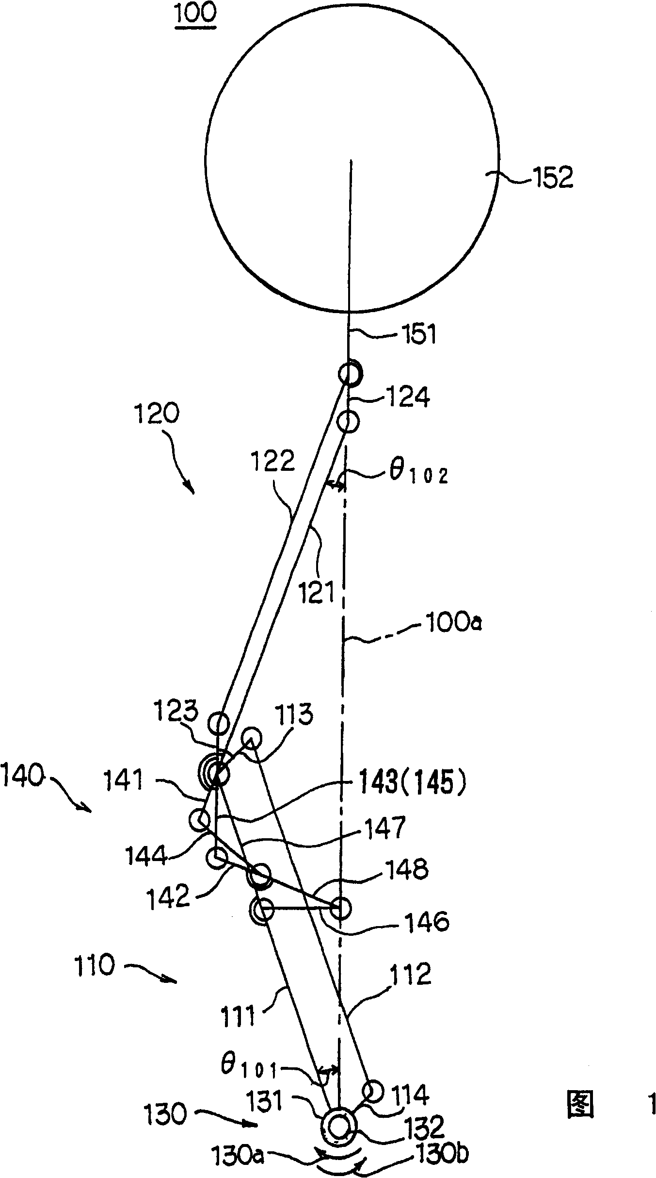
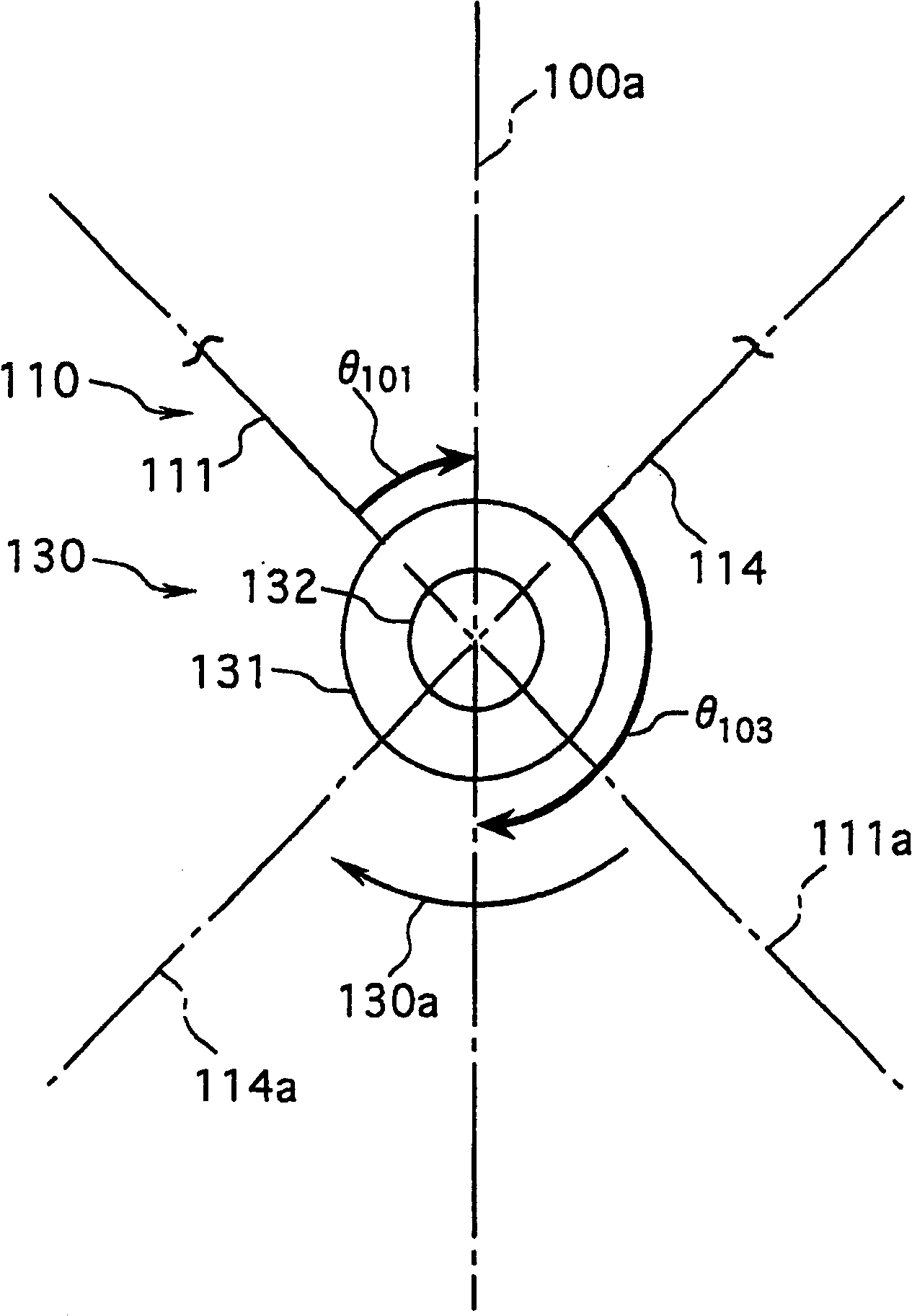
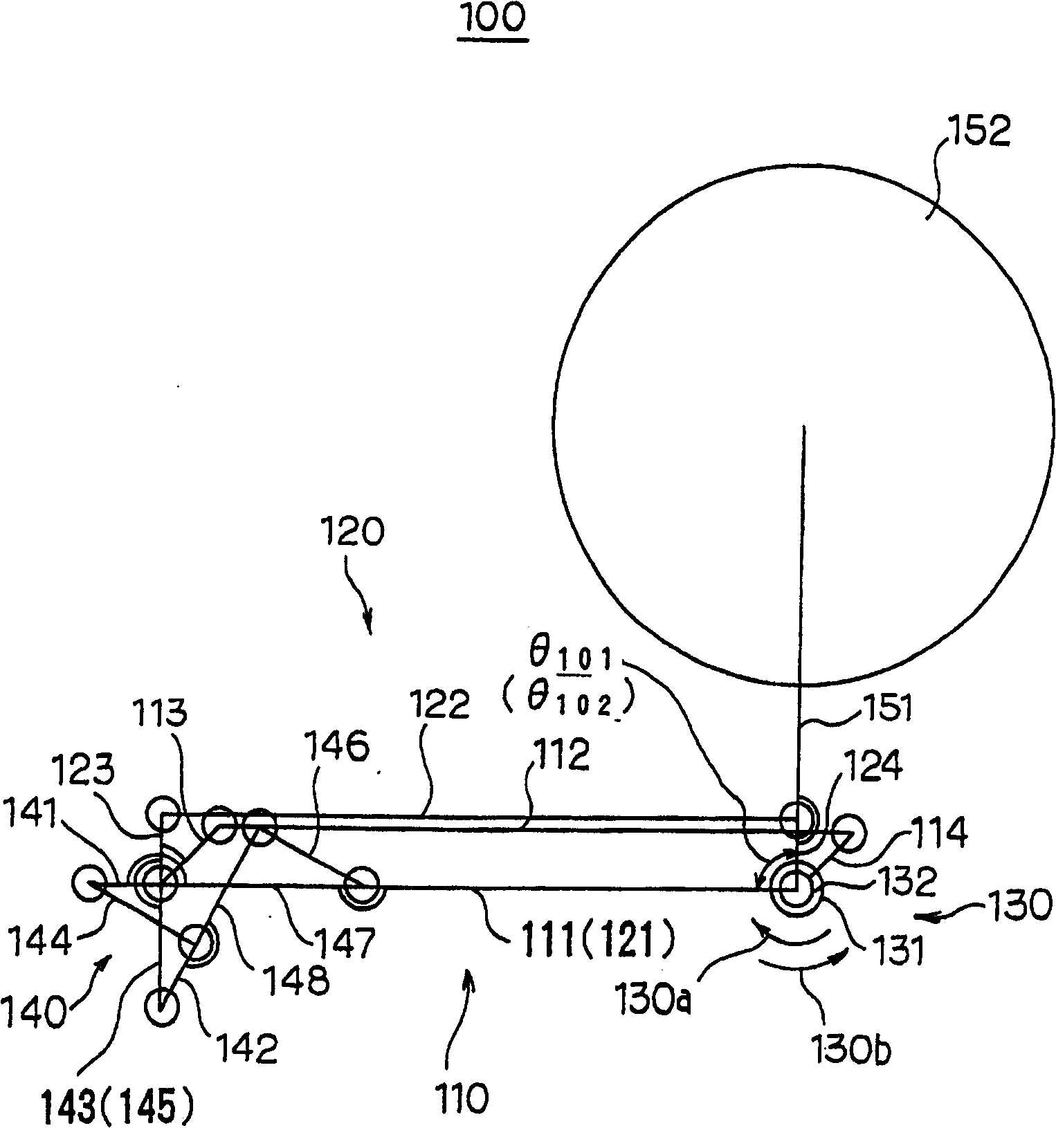
[0054] 1 to 4 show a first preferred embodiment of the manipulator device 100 of the present invention. The first embodiment of the manipulator device 100 shown in Figure 1 comprises a first arm linkage mechanism 110, a second arm linkage mechanism 120, a linkage holding mechanism 140, a manipulator drive mechanism 130, a manipulator component 151 , and a transmission component 152 .

[0055] The first arm linkage mechanism 110 consists of a four-bar crank chain, which includes a first arm link 111, a second arm link 112, a third arm link 113, and a first arm link 113. Four arm links 114 , wherein the second arm link 112 is substantially parallel to the first arm link 111 , and the fourth arm link 114 is basically parallel to the third arm link 113 . The second arm linkage mechanism 120 is composed of a second four-bar crank chain, which ...


PUM


Abstract

Herein disclosed is a robot arm mechanism (100) comprising a first arm link mechanism (110) and a second arm link mechanism (120), a robot arm driving mechanism 130 for driving the first arm link mechanism (110) and the second arm link mechanism (120), and a link retaining mechanism (140) for pivotably retaining the first arm link mechanism (110) and the second arm link mechanism (120), in which a third arm link (113) and a fourth arm link (114) of the first arm link mechanism (110) are kept forward in a first rotation direction (130a), in which the first arm link mechanism (110) and the second arm link mechanism (120) are extended, thereby enabling to prevent the quadric crank chain constituting the robot arm mechanism (100) from being flattened out while the first arm link mechanism (110) and the second arm link mechanism (120) are extended, and improving resistance to deformation, in comparison with the conventional robot arm mechanism (900).

Description

technical field [0001] The invention relates to a manipulator device with a telescopic arm, more specifically, a manipulator device with an arm drive mechanism capable of driving the manipulator to realize telescoping. Background technique [0002] At present, various conventional manipulator devices have been used in the manufacturing process of semiconductors, in which the manipulator is manipulated to make the arm telescopically move to work and process the workpiece. These workpieces, including wafers and other precision parts, are transferred by robotic devices and placed on work tables. [0003] A typical conventional robot device is disclosed in Japanese Patent Publication No. 2000-208588. Such as Figure 20 As shown, it includes a first arm linkage mechanism 910 , a second arm linkage mechanism 920 , a manipulator drive mechanism 930 and a link holding mechanism 940 . [0004] The first arm linkage 910 consists of a four-bar crank chain comprising a first arm link ...

Claims


Application Information

Patent Timeline
Patent Type & Authority Patents(China)
IPC IPC(8): B25J9/06B25J17/00B25J9/10F16H21/44H01L21/677
CPCY10S414/13B25J9/1065Y10T74/20329B25J9/06
Inventor 森弘树渡边彻也奥野长平
Owner NABLESCO CORP
Learn More