Piston with pressure-reducing piston ring
A technology for piston rings and piston ring grooves, which is applied to piston rings, pistons, cylindrical pistons, etc., can solve the problems of large energy consumption and friction loss, and achieve the effects of reducing energy consumption, reducing frictional resistance, and enhancing the sealing effect
- Summary
- Abstract
- Description
- Claims
- Application Information
AI Technical Summary
Problems solved by technology
Method used
Image
Examples
Embodiment 1
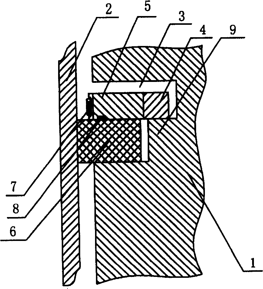
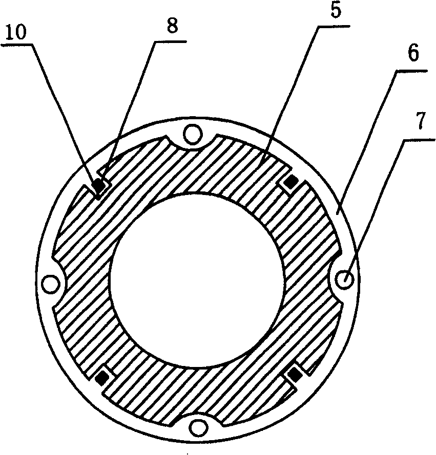
[0062] Embodiment 1: as figure 1 , figure 2 As shown, the piston with a decompression piston ring includes a piston body 1, a piston ring groove 3 on the piston body 1, and a piston ring in the piston ring groove 3, and the piston body 1 with the piston ring is set in the cylinder 2. The piston ring groove 3 is a stepped annular groove with two different groove depths, the upper groove depth is larger, and the lower groove depth is small, so a step 9 is formed on the piston body 1 . The piston ring is divided into an outer ring 5 arranged in the upper section of the piston ring groove 3, an inner ring 4 sleeved in the outer ring 5, and an outer tension ring 6 arranged in the lower section of the piston ring groove 3. The outer ring 5 and the inner ring 4 have the same thickness, but the thickness of both is less than the height of the upper section of the piston ring groove 3, and the inner diameter of the inner ring 4 is larger than the diameter of the piston body 1 at the ...
Embodiment 2
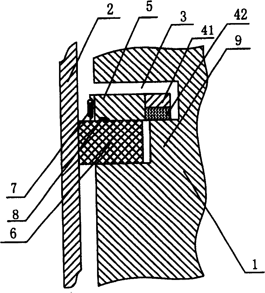
[0066] Embodiment 2: as image 3 As shown, the basic structure is the same as in Embodiment 1, wherein the inner ring 4 is composed of an inner first ring 41 and an inner second ring 42 of the same size stacked up and down.
Embodiment 3
[0067] Embodiment 3: as Figure 4 As shown, the basic structure is the same as that in Embodiment 2, wherein the outwardly stretched ring 6 is composed of a first outwardly stretched ring 61 and a second outwardly stretched ring 62 stacked up and down. There is a triangular notch on the outside of the cross-section of the first ring 61 and the inner wall of the cylinder 2. The outer side of the upper end surface is in contact with the inner wall of the cylinder 2, and the lower end of the spring 7 is fixed on the upper end surface; The diameter of the inner wall of 2 is equivalent, the outer diameter of the lower end surface is equivalent to the outer diameter of piston body 1, and its cross-section is an upwardly inclined flat head oblique cone.
PUM
 Abstract
Description
Claims
Application Information
 - R&D
- Intellectual Property
- Life Sciences
- Materials
- Tech Scout
- Unparalleled Data Quality
- Higher Quality Content
- 60% Fewer Hallucinations
Browse by: Latest US Patents, China's latest patents, Technical Efficacy Thesaurus, Application Domain, Technology Topic, Popular Technical Reports.
© 2025 PatSnap. All rights reserved.Legal|Privacy policy|Modern Slavery Act Transparency Statement|Sitemap|About US| Contact US: help@patsnap.com


