Hydrodynamic coupling with a speed protection mechanism and turbocompound system
A hydraulic coupler, coupler technology, applied in clutches, clutches, automatic clutches, etc., can solve problems such as impractical, damaged turbines, etc.
- Summary
- Abstract
- Description
- Claims
- Application Information
AI Technical Summary
Problems solved by technology
Method used
Image

Examples
Embodiment Construction
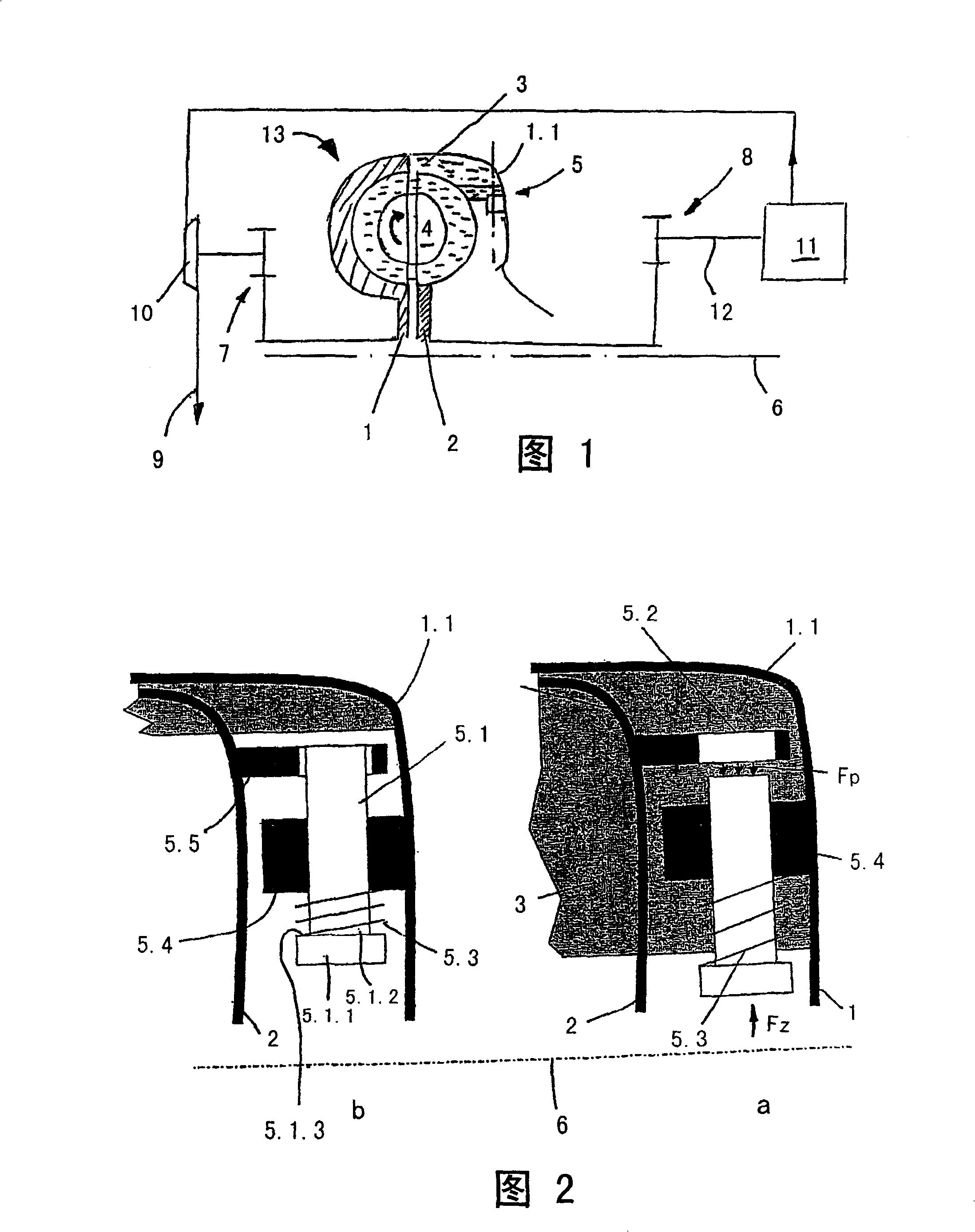
[0066] FIG. 1 shows a hydrodynamic coupling 13 which is arranged in the drive connection between a crankshaft driven by an internal combustion engine 11 and an exhaust gas utilization turbine 10 charged with exhaust gas from the internal combustion engine 11 . The fluid coupling 13 includes a pump wheel 1 and a turbine wheel 2 . The pump wheel 1 is drivingly connected to the exhaust gas utilization turbine 10 through a gear transmission 7 . The turbine wheel 2 is drive-connected via a gear transmission 8 to a crankshaft 12 .
PUM
 Abstract
Description
Claims
Application Information
 - R&D
- Intellectual Property
- Life Sciences
- Materials
- Tech Scout
- Unparalleled Data Quality
- Higher Quality Content
- 60% Fewer Hallucinations
Browse by: Latest US Patents, China's latest patents, Technical Efficacy Thesaurus, Application Domain, Technology Topic, Popular Technical Reports.
© 2025 PatSnap. All rights reserved.Legal|Privacy policy|Modern Slavery Act Transparency Statement|Sitemap|About US| Contact US: help@patsnap.com