
ATM data transmission system and data transmission method

A technology of a data transmission system and a data transmission method, which is applied in the direction of data exchange through path configuration, time division multiplexing selection device, ring network, etc., and can solve the problems of not adopting unified management and allocation of resources, lack of intelligence, and poor performance, etc. problems, to achieve the effect of access capability and resource occupation, cost saving, and effective management

Inactive Publication Date: 2008-10-22
MAIPU COMM TECH CO LTD
View PDF4 Cites 0 Cited by
  • Summary
  • Abstract
  • Description
  • Claims
  • Application Information

AI Technical Summary

Problems solved by technology

[0006] 1) Since the bandwidth resources on this ring are limited, the nodes on the ring share the ring in the manner of statistical multiplexing, and the resource occupation of the bandwidth is competitive; no corresponding mechanism is adopted to ensure that the resources are reasonable Unified management and allocation; the communication traffic between such peer nodes cannot be effectively allocated, and it is not suitable for the situation where the ring is used for ATM access
[0007] 2) Since it is a closed-loop structure, each node extracts the data of its own node from the ring and forwards the data that does not belong to this node, which may cause an infinite loop of invalid data on the ring, which will affect the entire Ring performance adversely affected
[0008] 3) There is no reliable packet-level state maintenance mechanism among the nodes on the ring, so they can only rely on the underlying transmission as the basis for ring state management and maintenance. Such a structure lacks intelligence, making it difficult to maintain and manage the topology of the entire network. Difficult to extend functionality

Method used


Image

  • ATM data transmission system and data transmission method

Examples


Embodiment Construction

[0021] The technical solution of the present invention will be described in detail below in conjunction with the accompanying drawings and embodiments.

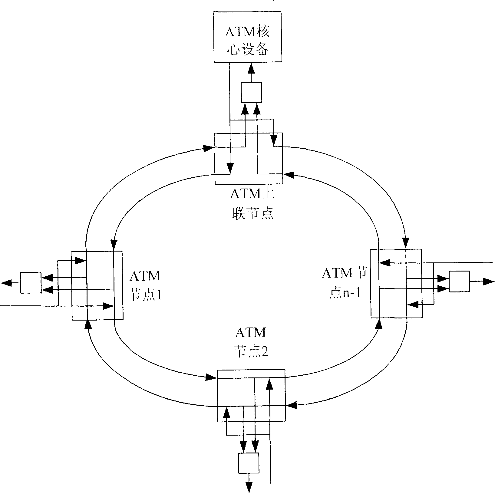
[0022] ATM data transmission system, comprises the ring network that N has the ATM node that two-way data transmission channel forms, it is characterized in that, in described N ATM nodes, there is an ATM uplink node; Described ATM uplink node is connected with ATM core equipment , for the data transmission of the ring network and the ATM core equipment and the operation management of the ring network; the ATM uplink node is the end point of the entire ring network data;

[0023] Further, there is a dedicated channel for transmitting network management information on the bidirectional data transmission channel between the ATM node and the ATM uplink node;

[0024] Furthermore, the registration information of the ATM node is stored in the ATM uplink node.

[0025] ATM data transmission method of the present invention, compris...


PUM


Abstract

This invention relates to data transmission network and to one ATM network structure and its data transmission method. This invention provides one ATM ring network, which divides ATM ring network points into upper and down types and when upper points are connected to core device as management points in charge for maintenance topological and dispatching materials as ring data terminal points connected to other device.

Description

technical field [0001] The invention relates to a data transmission network, in particular to a ring-shaped ATM (Asynchronous Transfer Mode) network structure and a data transmission method thereof. Background technique [0002] U.S. Patent No. 6,442,134B1 "ATM Network with Ring Architecture" (disclosure date: on August 27, 2002), describes such a ring network architecture: a plurality of nodes are connected into a ring, and on each node, a For the reverse packet ring. Each node extracts the data belonging to the node from the ring, forwards the data not belonging to the node directly, and adds the data to be sent through the node to the ring. Each node can both send data to and receive data from the two rings. [0003] When each node broadcasts to two rings to send the data accessed through the node, if the status of the two rings is normal, the node on the ring selects one of the rings to receive the data; if there is an error in one ring, then Select the ring without e...

Claims


Application Information

Patent Timeline
Patent Type & Authority Patents(China)
IPC IPC(8): H04L12/43H04Q11/04
Inventor 程常清
Owner MAIPU COMM TECH CO LTD
Learn More