Laser material processing machine tool

A machine tool and laser system technology, applied in laser welding equipment, metal processing equipment, manufacturing tools, etc., to achieve the effect of large working space, flexible transmission, and simple equipment

Inactive Publication Date: 2008-08-13
JIANGSU UNIV
View PDF9 Cites 0 Cited by
  • Summary
  • Abstract
  • Description
  • Claims
  • Application Information

AI Technical Summary

Problems solved by technology

[0003] The invention provides a laser processing machine tool suitable for the characteristics of laser cutting and welding, which fully combines the advantages of the parallel motion mechanism and the characteristics of optical fiber transmission, realizes the flexibility of laser processing, and overcomes the limitations of the current traditional laser processing machine tools and laser processing robots. Bringing defects

Method used


Image

  • Laser material processing machine tool
  • Laser material processing machine tool
  • Laser material processing machine tool

Examples


Embodiment Construction

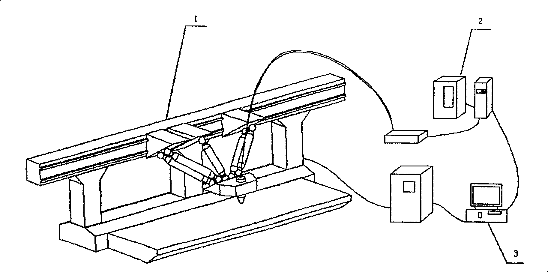
[0015] Laser processing machine tool of the present invention such as figure 1 As shown, it is mainly composed of a parallel machine tool 1, a laser system 2 and a control system. The control system is a control computer 3, one end of the communication line is connected to the parallel machine tool control cabinet 9, and the other end is connected to the laser system power supply and the controller 16.

[0016] Its working principle is that the control computer 3 sends a control command, one end is sent to the parallel machine tool control cabinet 9, and the other end is sent to the power supply and controller 16 of the laser system. The parallel machine tool control cabinet 7 analyzes and processes the control commands sent by the control computer 3, and generates CNC commands to control the parallel connection through contour modeling→G code generation→G code format conversion→interpolation→coordinate transformation→kinematic transformation→servo control. The drive slider 5...


PUM


Abstract

The present invention relates to a laser processing machine tool. Said machine tool adopts a new-type three-traslation-freedom parallel motion mechanism. It is characterized by that on the movable platform a laser beam focalizer is mounted, and a flexible transmission line of fiber is added, so that it can implement laser cutting and welding works.

Description

technical field [0001] The invention relates to the field of laser cutting and welding, in particular to a laser processing machine tool, which can realize high-precision and high-efficiency processing of plate parts. Background technique [0002] At present, traditional laser processing machine tools mainly include laser processing host, laser, light guiding and focusing system, numerical control system and automatic programming software. Among them, the laser processing host adopts traditional serial motion mechanism, such as Chinese patents ZL94190003.7 and ZL02802098.7, The mechanism is generally an asymmetric "C" layout composed of bed, machine column, spindle box and worktable in series. Due to the existence of cantilever components in this mechanism, the cantilever components need to bear a large bending moment. And torque, so it is difficult to obtain high structural rigidity. In addition, the mechanism itself has inherent defects such as large moving mass and linear...

Claims


Application Information

Patent Timeline
Patent Type & Authority Patents(China)
IPC IPC(8): B23K26/00B23K26/04B23K26/08B23K26/42B23K26/70
Inventor 王霄林跃强刘会霞蔡兰
Owner JIANGSU UNIV
Why Eureka
Try Eureka