Rapid-clamp driver

A driver and fast technology, applied in workpiece clamping devices, sorting, manufacturing tools, etc., can solve the problems of long time, inability to meet the sorting machine, complex structure, etc., to achieve convenient operation, shorten auxiliary time, and simple structure Effect

Inactive Publication Date: 2008-07-23
CHENGDU TOOL RES INST
View PDF6 Cites 0 Cited by
  • Summary
  • Abstract
  • Description
  • Claims
  • Application Information

AI Technical Summary

Problems solved by technology

The existing lever holder and elastic holder have complex structures, and the installation of the workpiece to be measured takes a lot of time, which is several times the measurement time, which cannot meet the requirements of the sorting machine

Method used


Image

  • Rapid-clamp driver
  • Rapid-clamp driver
  • Rapid-clamp driver

Examples


Embodiment Construction

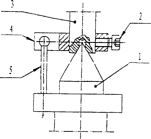
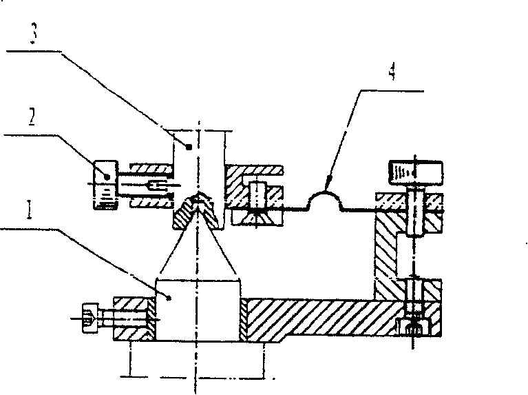
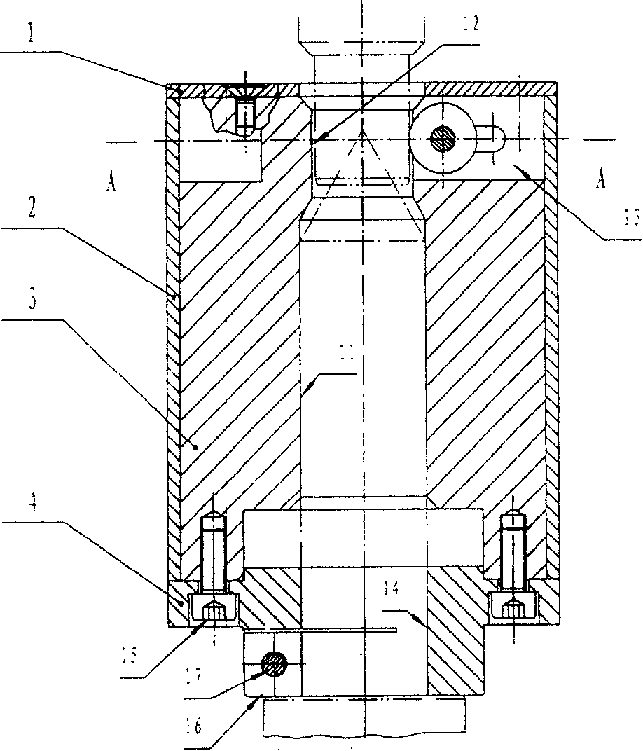
[0018] The fixing seat 4 and the driver seat 3 of the present invention are fastened together by M4 screws. Fasten the fixed base 4 coaxially with the main shaft of the sorting machine with M4 screws. The clamping mechanism consisting of bearing 5 (sliding bearing or deep groove ball bearing), pin shaft 6 and washer 7 is installed on the drive seat; the elastic stopper 8 is used to make the bearing 5 tightly pressed against the shaft of the measured shaft gear neck. After the shaft gear journal of the measured shaft is put into the inner hole of the driver, the upper center quickly pushes the journal center hole of the measured shaft gear into the center of the instrument main shaft. When the main shaft rotates, the driver rotates synchronously with it. Since the bearing 5 is tightly pressed on the journal of the measured shaft gear, the measured shaft gear also rotates synchronously with the main shaft. The inner hole of the driver seat 3 has chamfers, which is convenient ...


PUM


Abstract

The invention is about the quick clamp driving device which can solve the problem of the complex structure of the clamp device to save the time. The inner hole of the driving device seat is matched to the main shaft; the up hole matched to the gudgeon journal of the gear is the same axis with the inner hole. The many vertical slots with the shafting bearing in them are installed inside of the up hole uniformly. The rolling contour is matched to the sliding of the gear. The axis direction side is connected to the elastic stopper.

Description

Technical field: [0001] The present invention is related to the clamping device of the automobile shaft gear sorting machine. Background technique: [0002] Automobile shaft gear sorting machine, the measurement cycle of the gear on the shaft gear reaches <15 seconds. Therefore, placing the shaft gear on the measurement position, quickly clamping and driving the shaft gear to rotate is one of the important factors to improve the measurement cycle. The existing lever holder and elastic holder have complex structures, and the installation of the workpiece to be measured takes a lot of time, which is several times the measurement time, and cannot meet the requirements of the sorting machine. [0003] figure 1 For the lever holder. Before use, the driving rod 5 has been fastened on the spindle top 1. When inspecting the workpiece to be tested, the inspector must first fasten the shift fork 4 to the proper position of the journal of the workpiece 3 to be tested with the sc...

Claims


Application Information

Patent Timeline
Patent Type & Authority Patents(China)
IPC IPC(8): B25B11/00B07C5/00
Inventor 梁军邓上刘阳徐之江
Owner CHENGDU TOOL RES INST
Why Eureka
Try Eureka