
Capictance athermal flow-speed sensor based on micro mechanical technology

A flow velocity sensor, non-thermal technology, applied in fluid velocity measurement, instrument, velocity/acceleration/shock measurement, etc., can solve the problems of small range and inability to measure two-dimensional wind direction, achieve small temperature drift, improve sensitivity and resistance Interference ability, production method and simple structure effect

Inactive Publication Date: 2008-07-16
SOUTHEAST UNIV
View PDF6 Cites 0 Cited by
  • Summary
  • Abstract
  • Description
  • Claims
  • Application Information

AI Technical Summary

Problems solved by technology

At present, the common disadvantages of flow rate and direction sensors based on the non-thermal principle are the small range and the inability to measure two-dimensional wind direction.

Method used


Image

  • Capictance athermal flow-speed sensor based on micro mechanical technology
  • Capictance athermal flow-speed sensor based on micro mechanical technology

Examples


Embodiment Construction

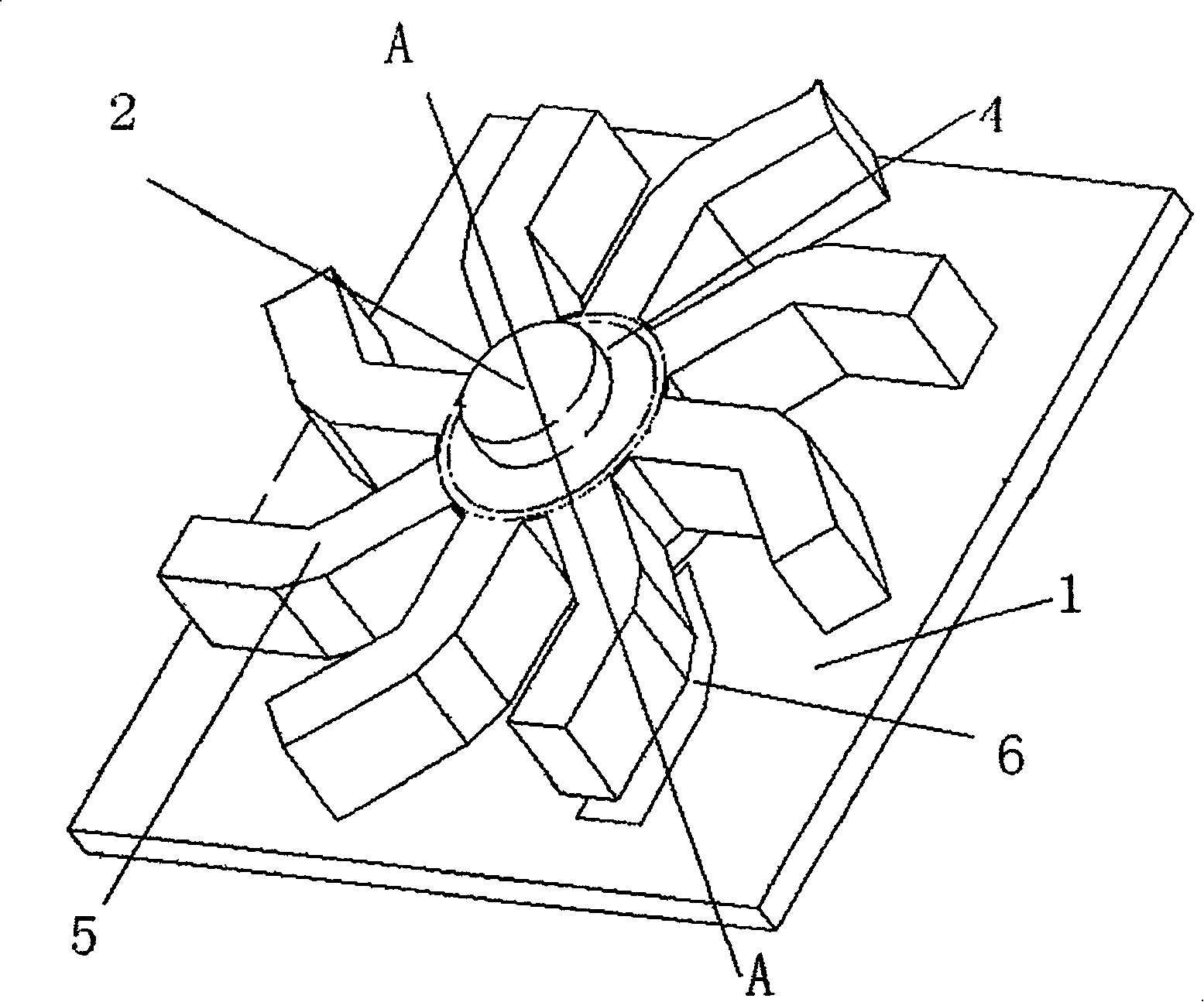
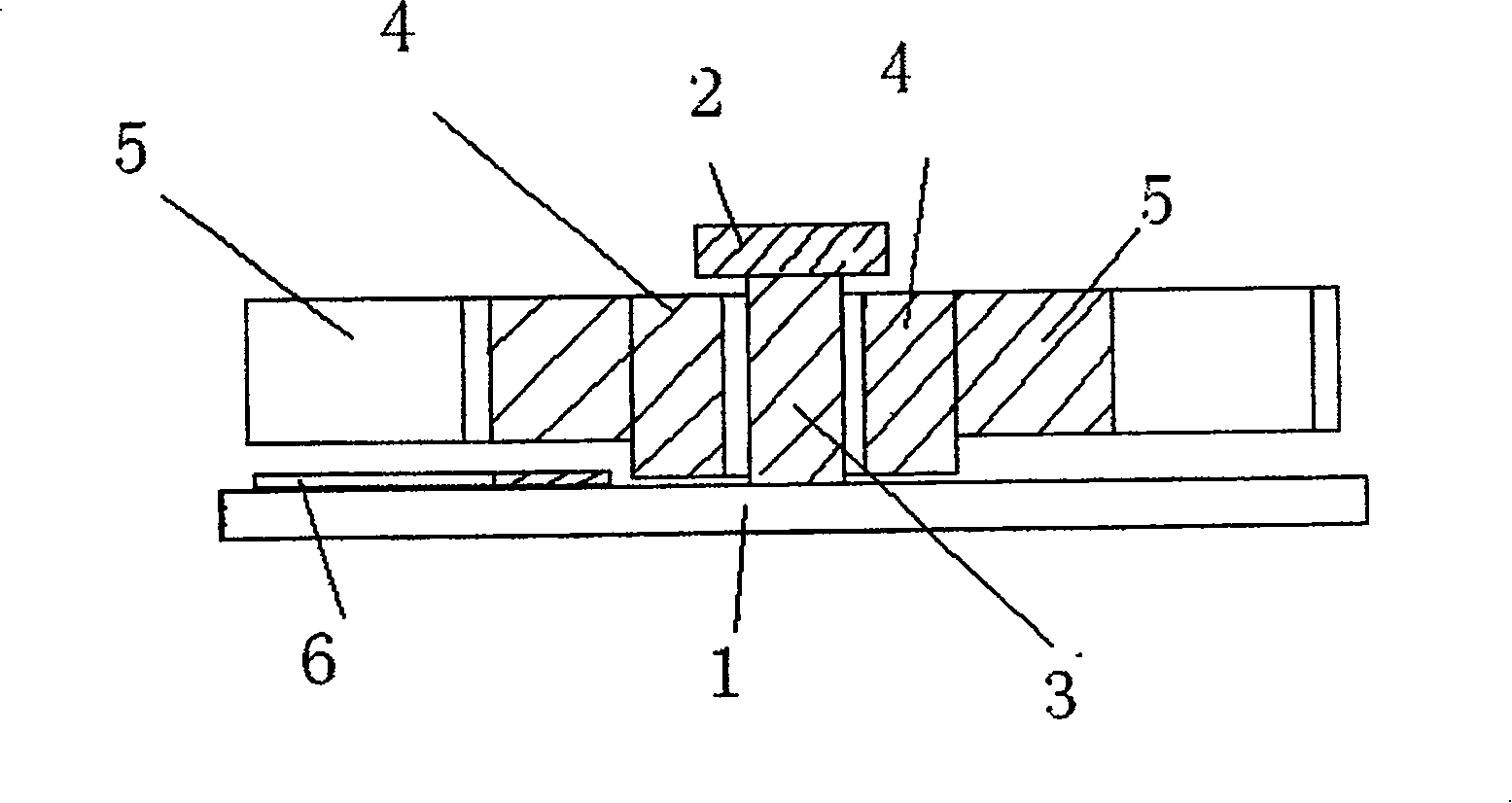
[0009] The invention is a sensor for measuring fluid velocity with an impeller structure. It consists of a glass bottom plate 1, a silicon top cover 2, a rotating shaft 3, a turntable 4, an impeller 5, a capacitor plate 6 and lead wires. The rotating shaft 3 is connected with the chassis and the top cover through a bonding process. The material of the shaft 3, the impeller 5 and the turntable 4 is conductive N-type semiconductor silicon, which is obtained by double-sided three-time etching, and a metal plate 6 is deposited on the corresponding glass surface under each impeller 5, and the impeller 5 itself conducts electricity and becomes another plate. A capacitor is formed between the conductive impeller 5 and the metal pole plate 6 . The impeller 5 relies on the contact of the rotating disk 4 and the rotating shaft 3 to lead wires from the glass base 1 . When the fluid flows through the impeller 5, it will drive the impeller 5 to rotate. The overlapping area of ​​the imp...


PUM


Abstract

The present invented flow-rate detector utilizes MEMS technical processing impeller to proceed detecting velocity of flow, which contains turntable glass chassis, silicon top cover, rotor shaft, turntable, impeller, and capacitor pole plate, wherein glass chassis fixed with rotor shaft, upper part of rotor shaft set with silicon top cover, rotor shaft outer side sleeved with turntable, turntable outer side fixed with impeller, upper surface of glass chassis set with capacitor pole plate. The material of Impeller and rotor shaft is N-type semiconductor silicon, which can be used as both of movable rotating member and one electrode for measuring capacitance. Said flow-rate detector adopts capacitance detection mode with advantages of small power consumption, large linear range, fast response, small temperature drift and reliability.

Description

technical field [0001] The invention relates to a micromechanical (MEMS) non-thermal flow velocity sensor, in particular to a sensor for detecting flow velocity using an impeller processed by MEMS technology. Background technique [0002] Fluid measurement has important applications in industrial and agricultural production, meteorology, environmental protection, national defense, scientific research, aviation and other departments. Among them, flow velocity and direction measurement, as an important part of fluid measurement, has been developed for many years. There have been measurement methods such as wind cup and vane measurement, pitot tube measurement, float measurement, mechanical measurement, acoustic measurement, optical measurement, heat transfer measurement, and electromagnetic measurement. The micro flow rate and flow direction sensor based on MEMS processing technology has the characteristics of small size, low price and good product consistency, and it has beco...

Claims


Application Information

Patent Timeline
Patent Type & Authority Patents(China)
IPC IPC(8): G01P5/06G01P5/08
Inventor 秦明魏泽文黄庆安
Owner SOUTHEAST UNIV
Learn More