
Thermostatic dehumidifying method and equipment

A technology of constant temperature dehumidification and finned tubes, which is applied in the field of refrigeration system design and manufacture, can solve the problems of complex system, large energy consumption, and low control precision, and achieve the effect of simple structure, good economy, and avoiding repeated consumption

Inactive Publication Date: 2008-07-16
SOUTHEAST UNIV
View PDF11 Cites 0 Cited by
  • Summary
  • Abstract
  • Description
  • Claims
  • Application Information

AI Technical Summary

Problems solved by technology

[0003] Technical problem: The purpose of the present invention is to provide a constant temperature dehumidification device and method with high control precision, low energy consumption and good economic performance in order to solve the problems of large energy consumption, complex system and low control precision in existing dehumidification devices

Method used


Image

  • Thermostatic dehumidifying method and equipment

Examples


Embodiment Construction

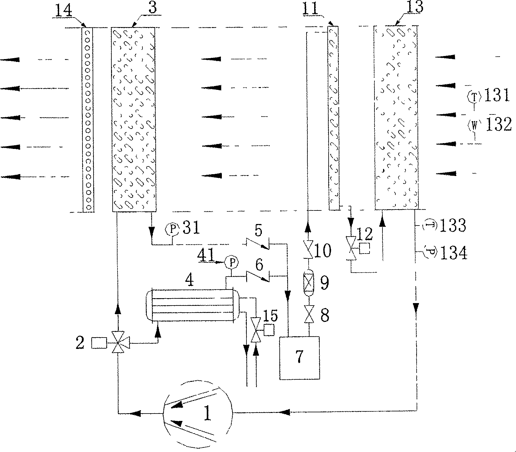
[0012] The flow chart of the constant temperature dehumidification device system is as follows: figure 1 As shown, the air inlet temperature is detected by the finned tube evaporator air inlet temperature sensor installed at the air inlet position of the device, and the air inlet humidity is detected by the finned tube evaporator inlet air humidity sensor. The input end of the variable capacity compressor 1 is connected to the output end of the finned tube evaporator 13, and the output end of the finned tube evaporator 13 is respectively connected to the finned tube condenser 3 and the The input end of the shell-and-tube heat exchanger 4, the output end of the fin-tube condenser 3 is connected to the liquid reservoir 7 through the first one-way valve 5, and the output end of the shell-and-tube heat exchanger 4 is connected through the second one-way valve 6 is connected to the liquid storage device 7, the output end of the liquid storage device 7 passes through the first shut-...


PUM


Abstract

Thermostatic dehumidifying method and equipment relate to a thermostatic dehumidifying method and a device realizing the method, wherein the method of the thermostatic dehumidifying equipment is that: after the refrigeration agent being compressed by the compressor, it is changed into the high temperature and high pressure refrigeration agent superheated vapor and after being discharged from the compressor, the refrigeration agent will pass through the three way electronic control valve. The three way electronic control valve divides the refrigeration agent into two parts: one part of the refrigeration agent enters the shell tube heat exchanger, wherein the refrigeration agent is condensed into the fluid to enter the reservoir through the second check valve; other part of the refrigerati on agent will enter the finned tube condenser to condense and output heat, wherein it is condensed into the fluid oneself passing through the first check valve to enter the reservoir. The refrigeration agent in the finned tube type condenser exchanges heat with the air and heats the air to the required air supplying temperature. The refrigeration agent is supercooled through the electronic expanding valvethrottle to flow into the finned tube type evaparator for evaparating. The refrigeration agent exchanges heat with the air in the finned tube type evaparator to make the air realize the thermostatic dehumidifying.

Description

technical field [0001] The invention relates to a constant temperature dehumidification method and a device for realizing the method, and belongs to the technical field of refrigeration system design and manufacture. Background technique [0002] With the rapid development of the national economy and the continuous improvement of people's living standards, people have higher and higher requirements for the comfort of living and working environments, and not only the temperature but also the humidity are also required to be controlled and adjusted. At the same time, the control of temperature and humidity in various industries is also the premise to ensure its normal production and operation. At present, the main way to adjust the temperature and humidity is to use the constant temperature and humidity unit to control. Among them, the main methods adopted for humidity control are freezing dehumidification, solution dehumidification, adsorption dehumidification and so on. Am...

Claims


Application Information

Patent Timeline
Patent Type & Authority Patents(China)
IPC IPC(8): F25B1/00
Inventor 梁彩华张小松
Owner SOUTHEAST UNIV
Learn More