Rotor balance structure of motor

A rotor balancing and balancing technology, applied in the control of mechanical energy, electrical components, electromechanical devices, etc., can solve the problem of limited radial rotation balance effect, maintain rotor rotation balance and start stability, ensure rotation efficiency, and prolong service life. Effect

Inactive Publication Date: 2008-07-02
SUNONWEALTH ELECTRIC MACHINE IND
View PDF2 Cites 0 Cited by
  • Summary
  • Abstract
  • Description
  • Claims
  • Application Information

AI Technical Summary

Problems solved by technology

Although the balance magnet ring has been set separately from the ring magnet of the rotor, the balance magnet ring or the balance magnetic permeable piece still only forms a magnetic attraction in one-dimensional direction, that is, only provides axial balance and radial rotation Balancing effects are still limited
In other words, when the rotor has a radial rotation offset, relying solely on the balance magnet ring to magnetically attract the balance magnetic plate cannot actively guide the rotor to actively return to the correct radial position

Method used


Image

  • Rotor balance structure of motor
  • Rotor balance structure of motor
  • Rotor balance structure of motor

Examples


Embodiment Construction

[0027] In order to make the above and other objects, features and advantages of the present invention more clearly understood, preferred embodiments of the present invention will be exemplified below and described in detail in conjunction with the accompanying drawings.

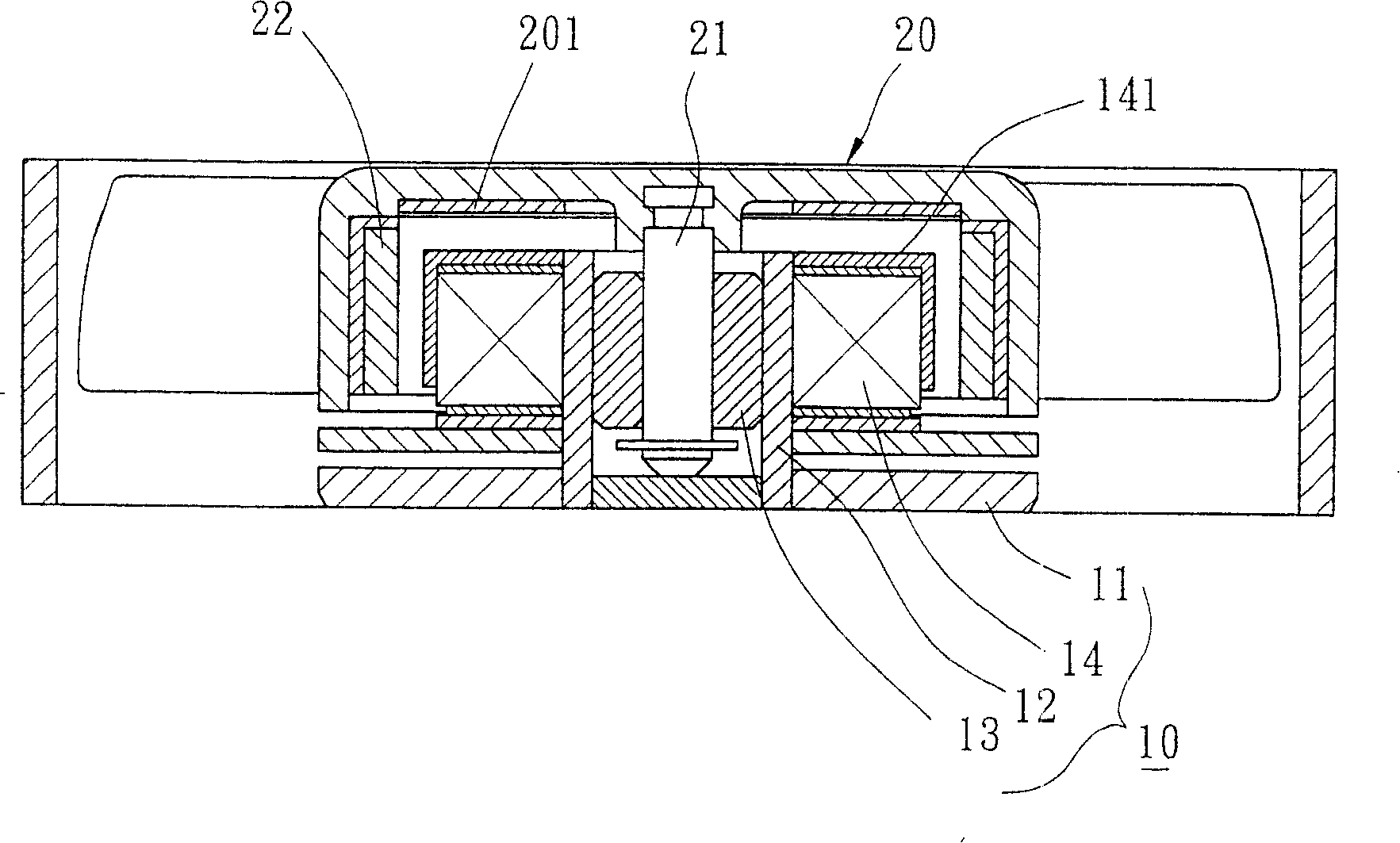
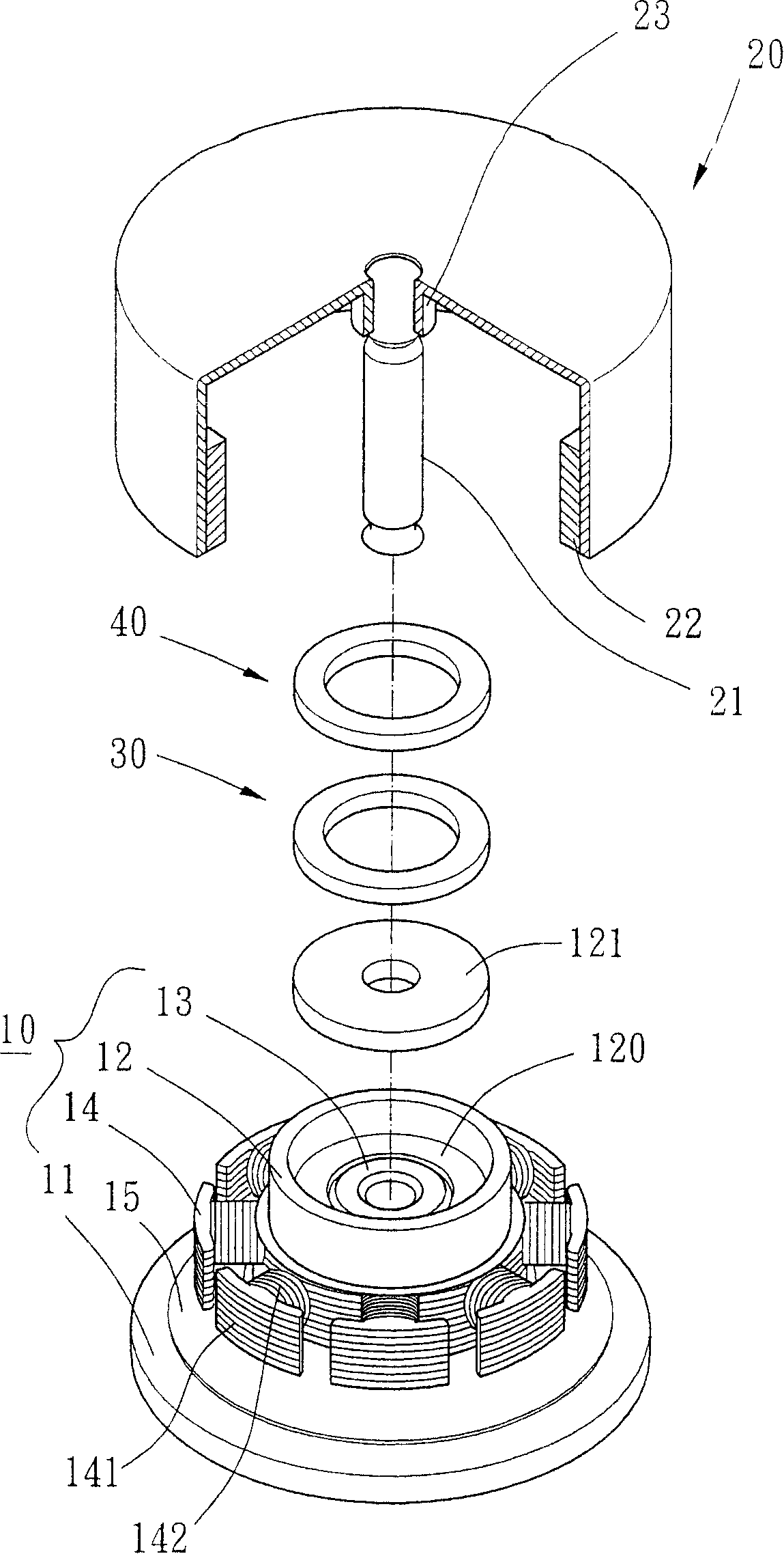
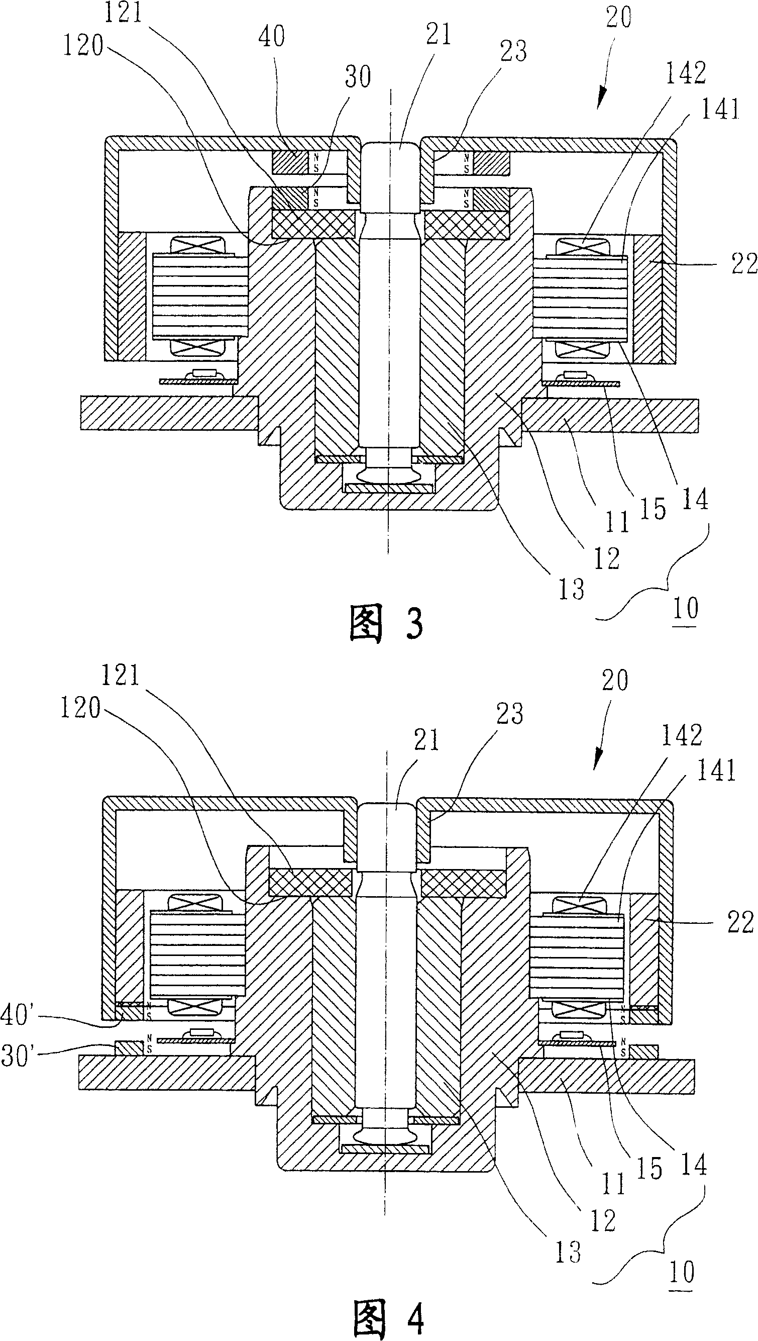
[0028] Please refer to figure 2 As shown, the rotor balance structure of the motor of the first embodiment of the present invention includes a fixed part 10, a rotor 20, a first balance magnet 30 and a second balance magnet 40, which can be applied to a spindle motor of a CD player or a small heat sink Motor fields such as fans.

[0029] Please refer to figure 2 As shown in FIG. 3 , the fixing part 10 of the first embodiment of the present invention is provided with a base 11 , a shaft tube 12 , a bearing 13 , a stator 14 and a circuit board 15 . The base 11 can be combined with a motor casing. The shaft tube 12 can be selected to be made separately or integrally formed on the base 11 directly. The insi...


PUM


Abstract

The present invention discloses a motor rotor balancing structure. It includes a fixing portion, a rotor, a first balance magnet and second balance magnet, said first and second balance magnet respectively set proper position of said fixing portion and rotor, adjacent surface of said first and second balance magnet having diversity polarity. Thereof said first and second balance magnetical adjacent surface attract on axial direction and radial direction, and then effectively keeping rotor rotational equilibrium and starting up stability.

Description

technical field [0001] The present invention relates to a rotor balance structure of a motor, in particular to a fixed part and a rotor utilizing a first balance magnet and a second balance magnet with different polarities to form axial corresponding magnetic attraction and radial magnetic attraction alignment , to maintain a balanced structure for rotor rotation stability. Background technique [0002] The rotor balance structure of the existing motor, such as the new patent of Taiwan Patent Publication No. 383818 "Radiator Fan Group Structure with Magnetic Positioning", please refer to figure 1 As shown, it includes a fixed part 10 , a rotor 20 and a magnetically sensitive metal sheet 201 . The fixing part 10 has a base 11 , a shaft tube 12 , a bearing 13 and a stator 14 . The shaft tube 12 is fixed on the base 11 , and the shaft tube 12 can accommodate the bearing 13 . The stator 14 is provided with several pole pieces 141 . The rotor 20 has a shaft 21 and a ring magn...

Claims


Application Information

Patent Timeline
Patent Type & Authority Patents(China)
IPC IPC(8): H02K7/04
Inventor 洪银树陈国祥
Owner SUNONWEALTH ELECTRIC MACHINE IND
Why Eureka
Try Eureka