Tyre mould
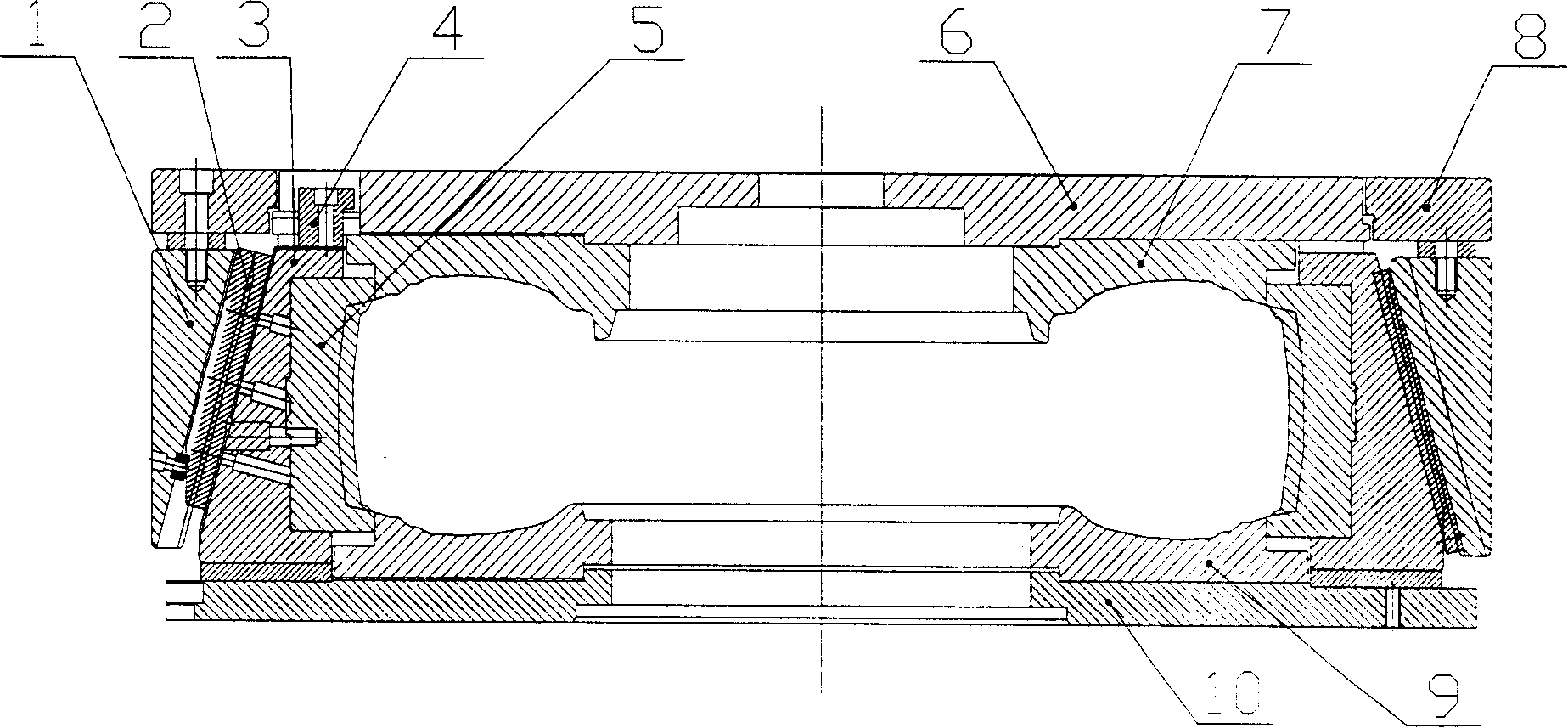
A technology of tire molds and mold sets, applied in the field of molds, which can solve the problems of high manufacturing costs, large vulcanization equipment, and large mold quality, and achieve the effects of reducing production costs, simple structure, and improving production efficiency
- Summary
- Abstract
- Description
- Claims
- Application Information
AI Technical Summary
Problems solved by technology
Method used
Image
Examples
Embodiment 1
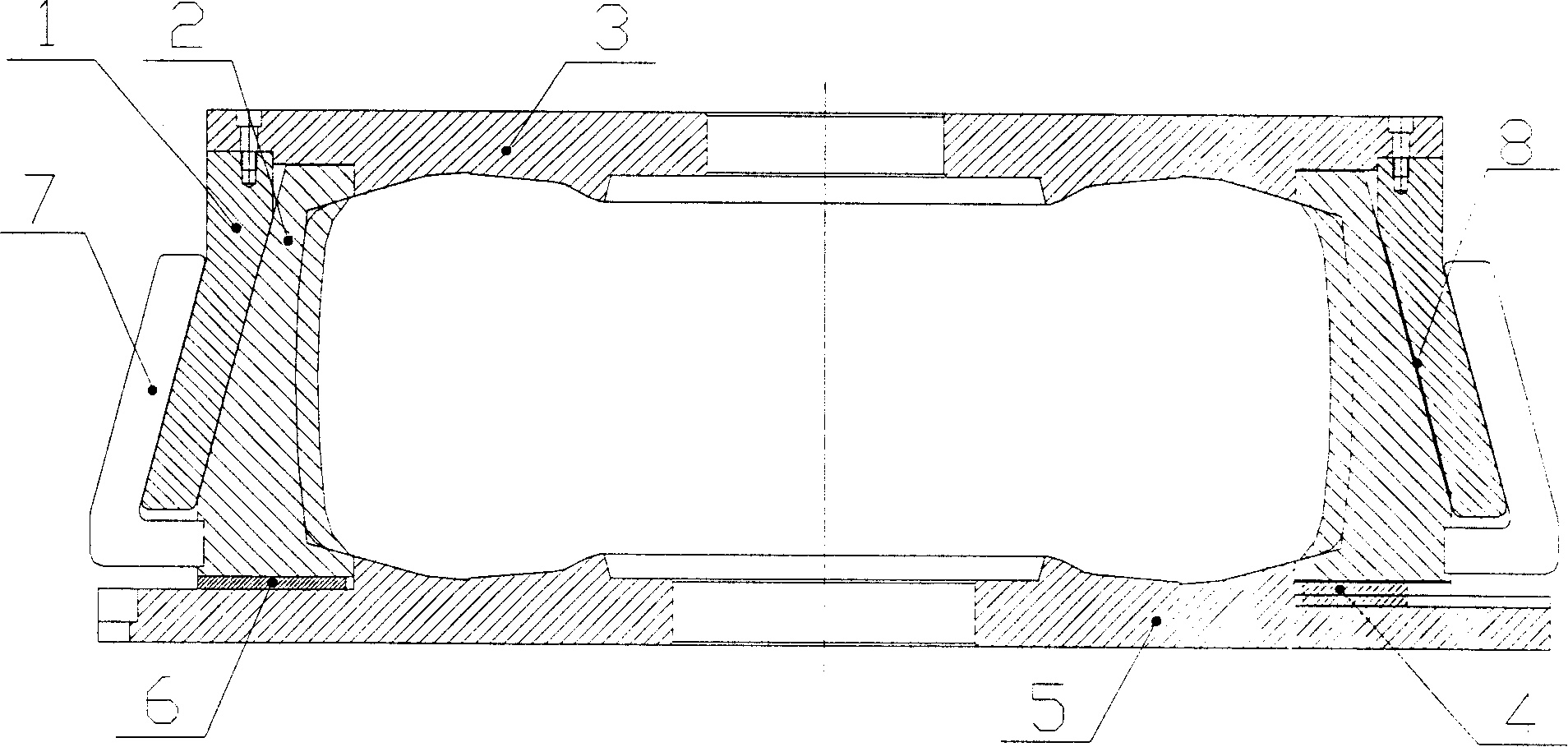
[0029] Such as figure 2 As shown, 1 is the middle mold cover, 3 is the upper side plate, 4 is the slider, 5 is the lower side plate, 6 is the anti-friction block, 2 is the pattern block, which is located between the upper side plate 3 and the lower side plate 5 A tire crown pattern is formed, pattern blocks 2 are evenly distributed on the same circumference, and a slide block 4 is fixed at the bottom thereof. The inclined surface of the outer surface of the pattern block 2 and the inclined surface of the inner surface of the middle mold sleeve 1 are relatively matched and slid, and the pattern block 2 and the lower side plate 5 are positioned and connected in the axial direction of the mold, and there is no axial displacement between them. 1. During the mold closing process, each pattern block can simultaneously reciprocate synchronously on the upper part of the lower side plate 5 along the radial direction of the mold. Plate 3 moves up and down. A plurality of pattern bloc...
Embodiment 2
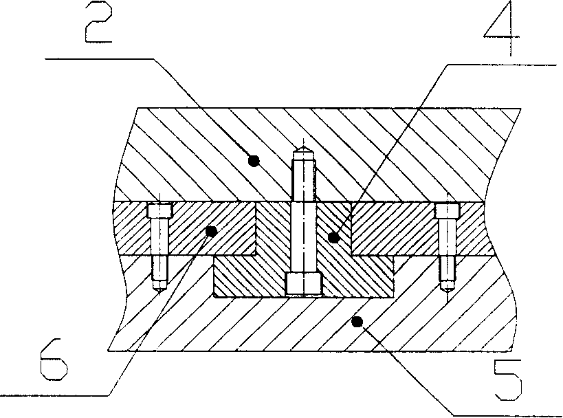
[0035] The connection mode between the pattern block 2 and the lower side plate 5 in the axial direction of the mold is as follows: Figure 4 As shown, the protrusion at the bottom of the pattern block 2 and the pattern block 2 form an integral structure. The groove is combined with two friction-reducing blocks 6 fixedly installed along the radial edge of the groove.
[0036] Others are the same as embodiment 1.
Embodiment 3
[0038] The connection mode between the pattern block 2 and the lower side plate 5 in the axial direction of the mold is as follows: Figure 5 As shown, the protrusion at the bottom of the pattern block 2 is integrated with the pattern block 2, and the section of the protrusion is dovetail-shaped, and the groove on the upper part of the lower side plate 5 is also a corresponding dovetail groove.
[0039] Others are the same as embodiment 1.
PUM
 Abstract
Description
Claims
Application Information
 - R&D
- Intellectual Property
- Life Sciences
- Materials
- Tech Scout
- Unparalleled Data Quality
- Higher Quality Content
- 60% Fewer Hallucinations
Browse by: Latest US Patents, China's latest patents, Technical Efficacy Thesaurus, Application Domain, Technology Topic, Popular Technical Reports.
© 2025 PatSnap. All rights reserved.Legal|Privacy policy|Modern Slavery Act Transparency Statement|Sitemap|About US| Contact US: help@patsnap.com


