Process for the purpose of determining surface evenness errors in band and particularly steel and metal band and further a surface evenness measuring roller

A technology of surface uniformity and error, applied in the field of measuring rolls for determining the surface uniformity error and surface uniformity in strips, especially steel strips and metal strips, and can solve problems such as small measurement accuracy

Inactive Publication Date: 2008-06-25
BWG BERGWERK & WALZWERK MASCHINENBAU GMBH
View PDF5 Cites 2 Cited by
  • Summary
  • Abstract
  • Description
  • Claims
  • Application Information

AI Technical Summary

Problems solved by technology

However, such strain gauges have a relatively small measurement accuracy compared to piezoelectric crystals

Method used


Image

  • Process for the purpose of determining surface evenness errors in band and particularly steel and metal band and further a surface evenness measuring roller
  • Process for the purpose of determining surface evenness errors in band and particularly steel and metal band and further a surface evenness measuring roller
  • Process for the purpose of determining surface evenness errors in band and particularly steel and metal band and further a surface evenness measuring roller

Examples


Embodiment Construction

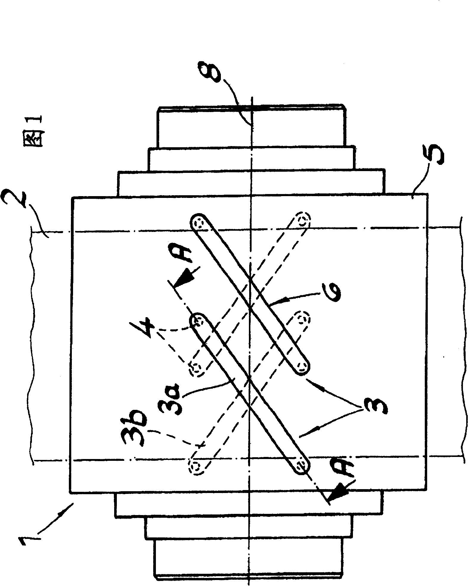
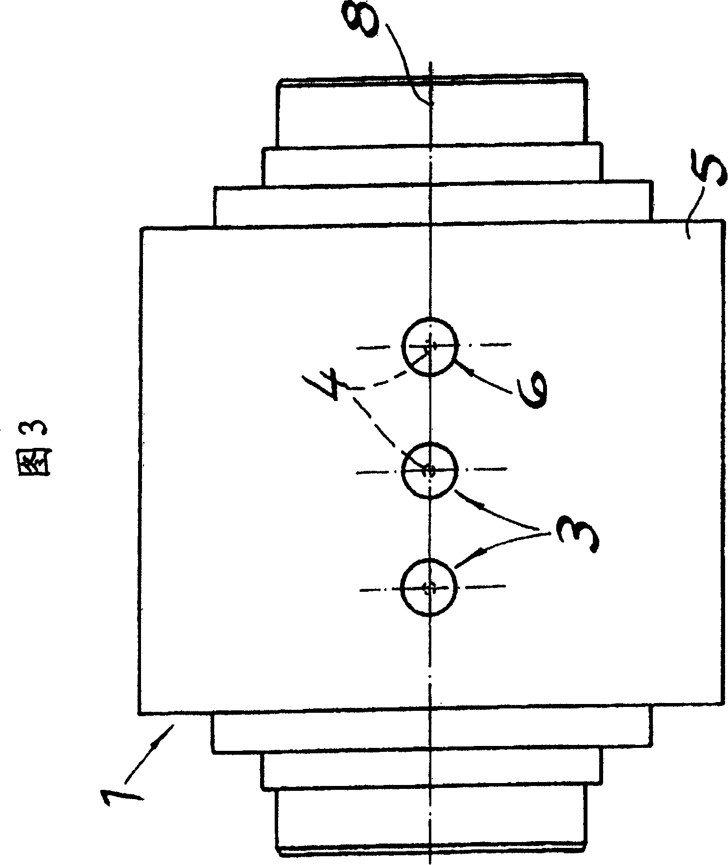
[0014] In FIGS. 1 to 4 there is shown a surface evenness sensor roll 1 for determining, in particular the steel strip and Surface uniformity errors in metal strips. Such a surface uniformity sensor roll comprises at least one measuring head 3 with two partial measuring heads joined together and offset by 180° each in the roll mantle and supported on two force transmitters and passed through A circular movement gap 6 is separated from the roll mantle 5 and fixed to each other by at least one tie rod 7, wherein the belt 2 surrounds the belt 2 with a predetermined contact arc during the measurement of the tensile stress distribution of the belt 2 over the entire belt width. around a surface uniformity sensor roller 1, thereby applying a local pressure to the surface uniformity sensor roller 1, wherein the belt 2 is subjected to tensile stress over its entire width, the local pressure corresponding to the local longitudinal tensile stress distribution in the direction of the belt,...


PUM


Abstract

A method and a surface evenness measuring roller for determining surface evenness measurement errors in steel and metal band comprising at least one measuring head having part measuring heads which part measuring heads are integrated respectively offset by 180 DEG into the roller mantel and supported on two force transmitters and are further separated from the roller mantle by means of a circumferential motion gap and are braced with respect to one another by means of at least one tie rod wherein in the course of a measurement of the band tensile stress distribution over the whole band width the band with band is subject to tension over its whole band width wraps around the surface evenness measuring roller with a predetermined arc of contact and thereby exerts pressing forces onto the surface evenness measuring roller from which pressing forces can be determined the band tension distribution.

Description

technical field [0001] The invention relates to a method for determining surface uniformity errors of strips, in particular steel strips and metal strips, as the strip passes, for example, through a strip processing line or a rolling mill train. Background technique [0002] The implementation of this method is known for example from EP 1369186A2, in which a surface evenness (evenness) measuring roll has at least one integrated beam sensor along the length of the roll. The longitudinal direction extends in a wavy line or in a straight line, in order to determine the tension of the belt acting on said roller, which belt partially surrounds the sensor roller, wherein, during the determination of the tension, the beam sensor with the start area and the end area is at least Occasionally within a contact arc formed by a strip and whose ends are supported on load cells and / or force transmitters. [0003] The beam sensor is fastened to the roll body with the aid of two preloading ...

Claims


Application Information

Patent Timeline
Patent Type & Authority Patents(China)
IPC IPC(8): B21B38/02B21B37/28G01L5/04
CPCB21B38/02G01L5/045B21B37/28B01D46/0027A01M1/14A61L9/205B01D53/88B01D46/4254B01D46/0045B01D46/44B01D2255/802B01D2259/804B01J35/39
Inventor A·诺埃
Owner BWG BERGWERK & WALZWERK MASCHINENBAU GMBH
Why Eureka
Try Eureka