
Antenna connector

A technology for antenna connectors and antennas, applied to antennas, antenna supports/mounting devices, electrical components, etc., can solve problems such as inability to cope with rotational operation force, uneven torque, short elastic change stroke, etc., and achieve uniform and stable torque And the effect of positioning effect, ease of change relationship, and long change range

Inactive Publication Date: 2008-06-18
ALFATEK ELECTRONICS
View PDF3 Cites 0 Cited by
  • Summary
  • Abstract
  • Description
  • Claims
  • Application Information

AI Technical Summary

Problems solved by technology

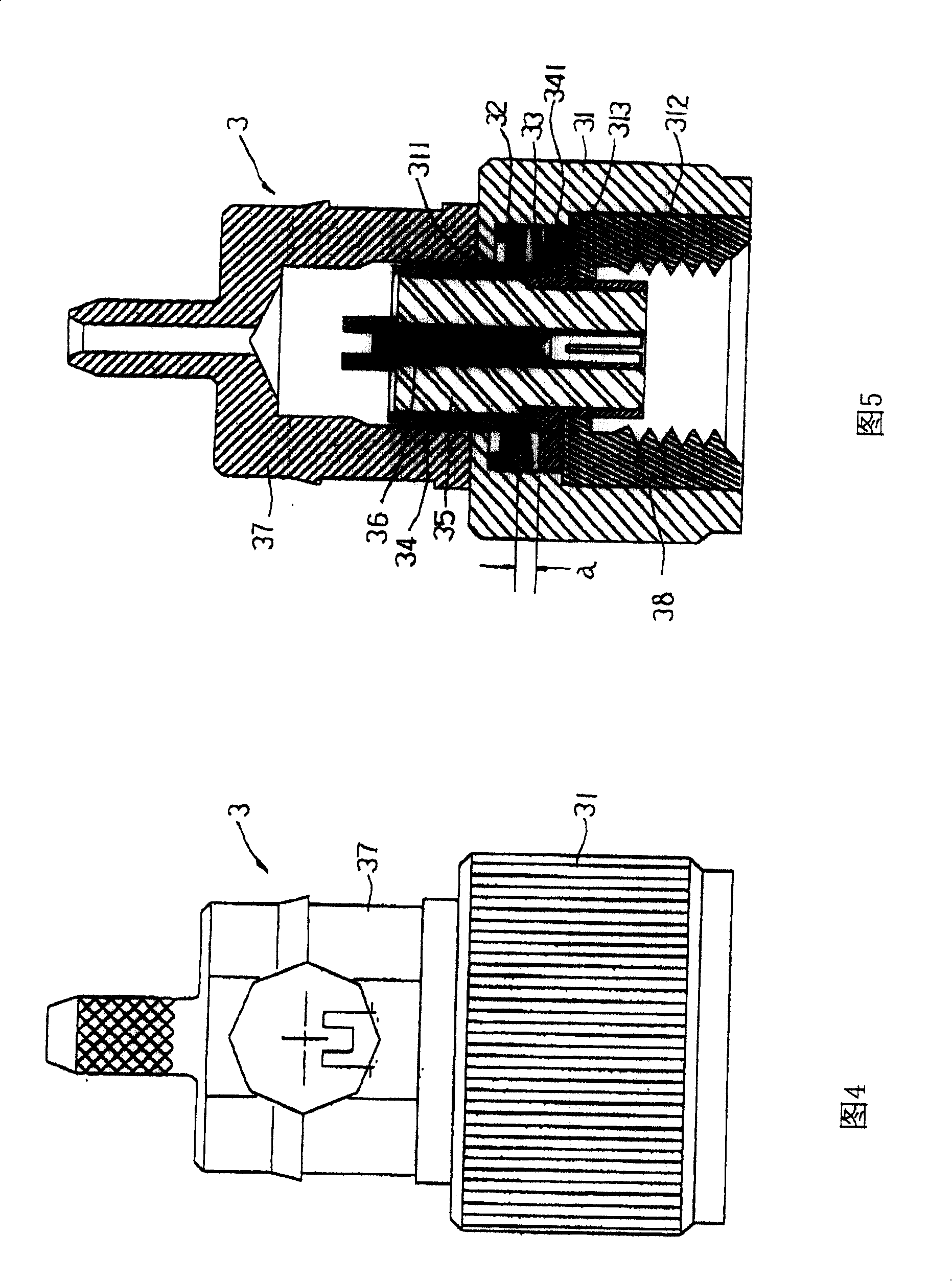
However, this conventional connector 3 has the following disadvantages in use: (1) The conventional connector uses a corrugated plate reed 33 as a torsion component, which is installed between the circular washer 32 and the outer protruding ring portion 341 In this certain space, the reed is deformed to obtain the torsion force, but the elastic change stroke of the reed 33 is short (its installation space a is also limited), and the relationship between its own deformation and torsion is too large. It is too sensitive, and the manufacturing tolerance of the parts cannot be accurately grasped. Therefore, it is difficult to obtain consistent torque; (2) The space generated by the torque is extremely small, and when rotating, the space will change, resulting in uneven torque. When responding to the rotation operation of the user, you will feel that the operation force is uneven, sometimes tight and sometimes loose; (3) the reed 33 is directly placed on the top surface of the protruding ring portion 341. When the antenna is rotated, the The reed 33 can rotate along with it, and though lubricating oil can be applied at the frictional rotation place, the reed 33 still can interfere with the adjoining assembly due to its wavy protruding piece rotating and cause abnormal rotation sound; (four ) between the joint assembly 38 and the shell 31, and between the ground connection pipe 34 and the rear cover body 37, are a tight fit combination, however, sometimes they will fall off due to improper control of the tight fit, which cannot cope with the rotation of the user. The rotating operation force brought during the adjustment will cause the antenna to fall off and be damaged, making it unusable; (5) when the joint assembly 38 is locked to the corresponding connector of the wireless device 1, it may be due to improper control of both parties (the length is too long or Misalignment) causes the ground connection pipe 34 to retreat, and squeezes the wave plate-shaped reed 33, causing the reed to be excessively deformed, so that when the antenna is to be adjusted, it will be too tight between the reed 33 and the protruding ring portion 341. It cannot be rotated, and its rotating force may cause the joint assembly 38 to be tightened or loosened between the wireless device 1; and, when the antenna is unscrewed, the reed 33 has been excessively deformed and cannot be restored to the original torque, making it unusable (6) The ground terminal signal of the wireless device 1 is transmitted to the negative terminal of the antenna through the joint assembly 38, the ground connection pipe 34, and the rear cover 37 in sequence, which is a multi-segment contact, and the grounding property is poor (7) Among its many components, some components are assembled in the shell 31 from bottom to top, and some components are assembled in the shell 31 from top to bottom, which is troublesome and inconvenient for its assembly

Method used


Image

  • Antenna connector
  • Antenna connector
  • Antenna connector

Examples


Embodiment Construction

[0061]The structure, features and effects of the present invention are further described in detail in accordance with the embodiments of the accompanying drawings as follows. 6 is a side view of the antenna connector of the present invention, and FIG. 7 is a cross-sectional view of the antenna connector of the present invention.

[0062] As shown in the figure, the antenna connector 4 of the present invention includes a cylindrical shell 41, a joint assembly 42, a grounded rear cover 43, a lower gasket 44, an upper fixed washer 45, a telescopic coil spring 46, A ground connection tube 47 , an insulating sleeve 48 , and a center terminal 49 .

[0063] The inner wall of the cylindrical shell 41 has an inner shoulder 411 at about the middle portion thereof, and the interior of the cylindrical shell is divided into a lower chamber 412 and an upper chamber 413 by the inner shoulder.

[0064] The above-mentioned joint assembly 42 has a body 421 which is closely fitted to the lower ...


PUM


Abstract

This invention relates to an antenna connector, which comprises a cylindrical housing with an inward shoulder in its inner wall, a bonding component close located in the housing with an evagination ring covering the shoulder of the housing, an earth back cover with its conical bevel located in the top of the bonding component, outward projecting from the housing, and owning an evagination ring covering the evagination ring of the bonding component, a lower pad located in the top of the evagination ring of earth back cover, a upper setting block located above the pad and fixed in the top of the housing and riveted, a flexible wound spring located between the upper pad and upper setting block, an earth connecting tube close located in the earth back cover, an insulating cover equipped in the earth connecting tube and a central terminal in the insulating cover. The invention has firm structure and accurate connection.

Description

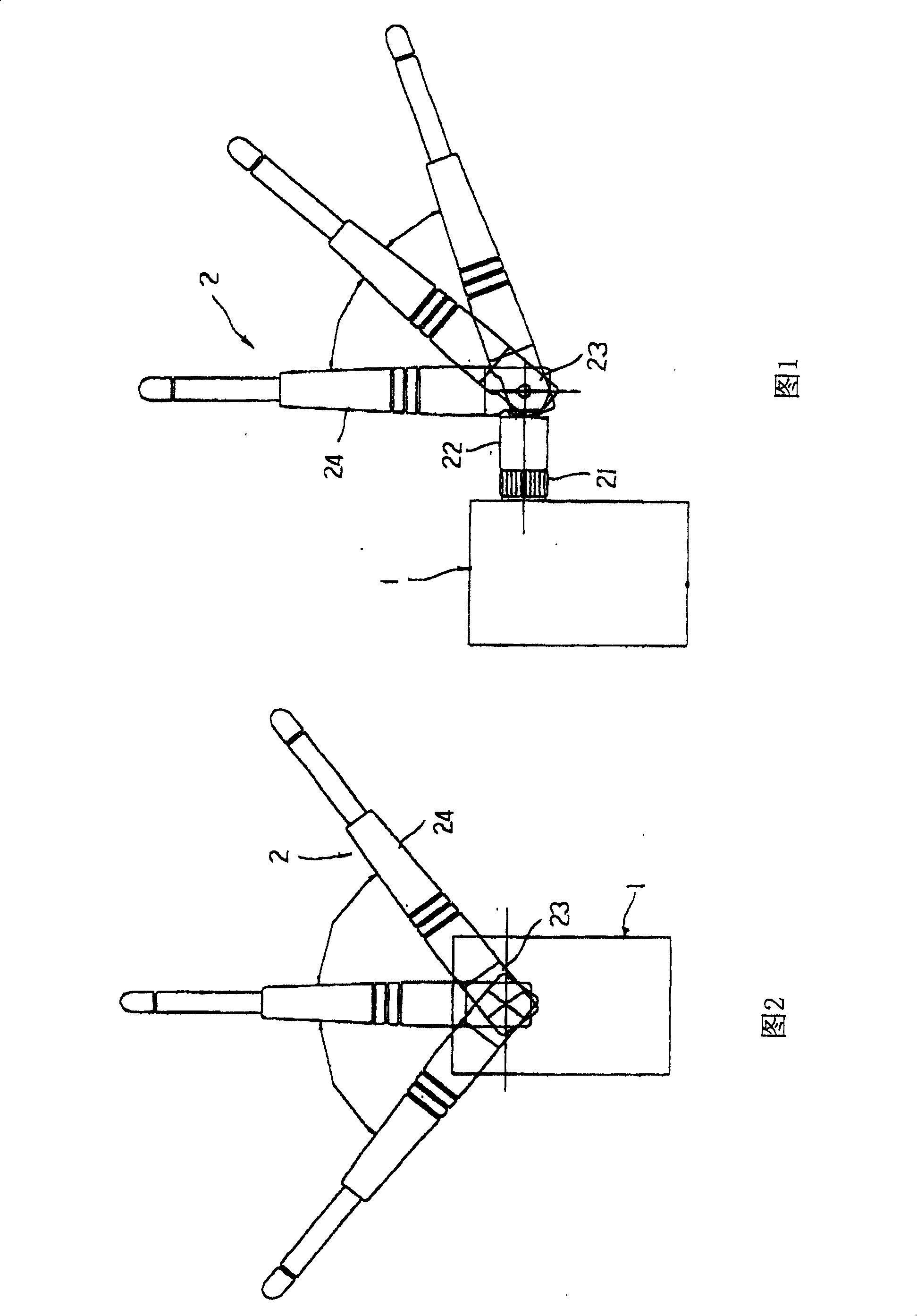
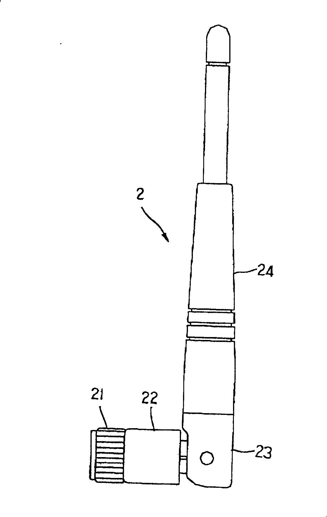
technical field [0001] The present invention relates to an antenna connector, in particular to a connector with strong structure, precise joint and good positioning quality of the antenna. Background technique [0002] In recent years, the development of wireless devices such as wireless networks has sprung up. The wireless device is used to send and receive signals through an antenna. Because radio frequency technology is used to transmit and receive wireless signals, and in order to obtain better communication quality, the antenna must be able to be adjusted in direction to obtain different radiation angles. [0003] Please refer to Figure 1 to image 3 As shown, the antenna structure 2 used by a wireless device 1 such as a wireless network generally includes a connector 21 which is connected to a corresponding connector structure (not shown) of the wireless device 1, and a fixing base 22 which is combined with the connector 21 is provided with a rotatable part, an upper...

Claims


Application Information

Patent Timeline
Patent Type & Authority Patents(China)
IPC IPC(8): H01Q1/12H01Q3/06
Inventor 周復民
Owner ALFATEK ELECTRONICS
Learn More