


Quick Research
Generate reliable direction feasibility study reports for your R&D in just a few steps.

Technical Q&A
Discover and master advanced knowledge NOW. Basics, ideas, possibilities, all at once.

Find Solutions
As an expert in R&D theories, this can generate solutions to your technical problems instantly.

Evaluate Feasibility
Analyze your overall solution with one click, know your potential R&D risks in advance.

Monitor Landscape
Get weekly tech updates, stay abreast of the latest tech innovations and key insights.
Flow structure of controlling liquid continuously flowing in micro-pipeline
A micro-pipeline, liquid technology, applied in fluid controllers, gas/liquid distribution and storage, piping systems, etc., to achieve the effect of easy implementation, reduced complexity and difficulty, and reliable effect
- Summary
- Abstract
- Description
- Claims
- Application Information
AI Technical Summary
Problems solved by technology
Method used
Image

Examples
Embodiment 1
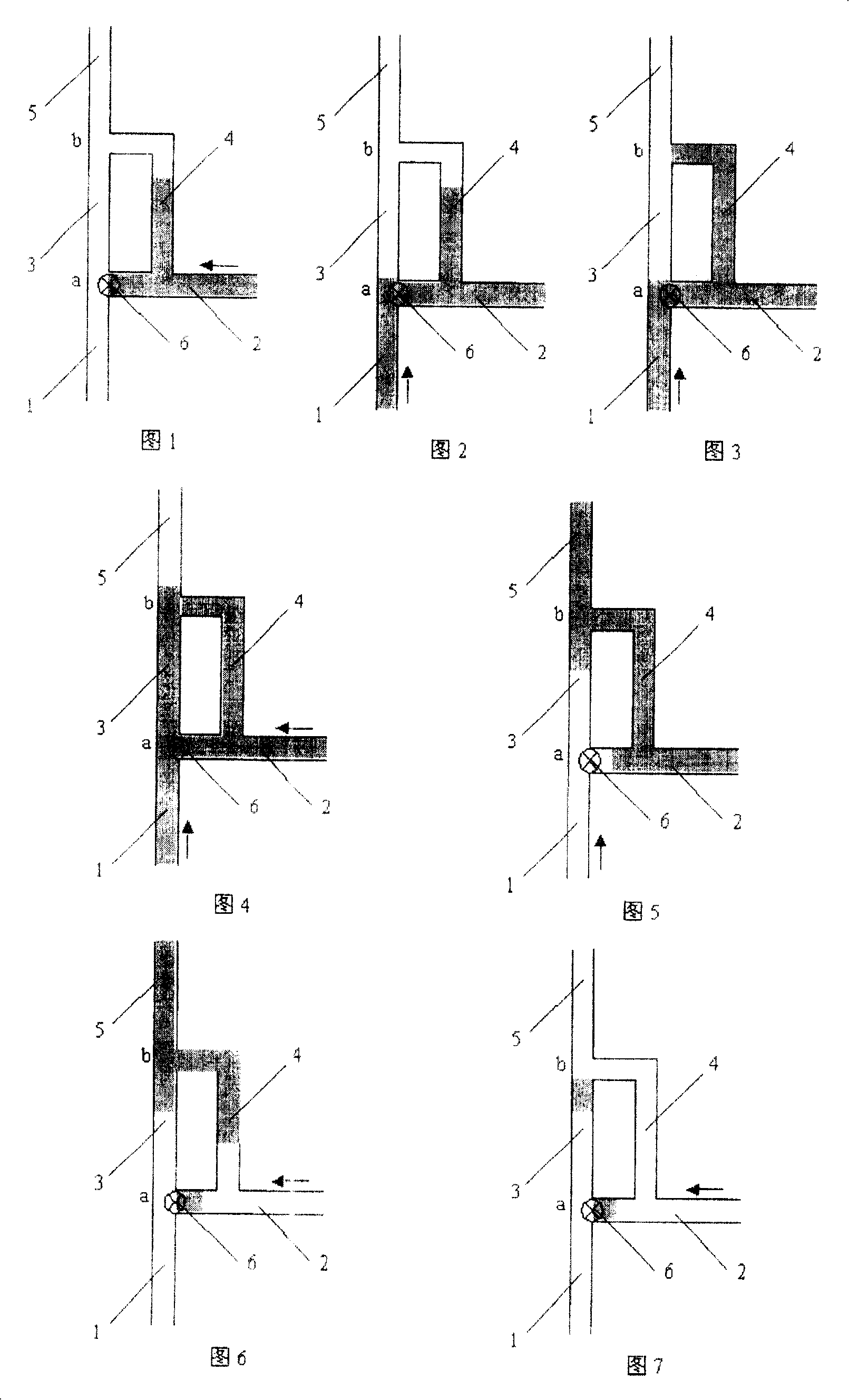
[0024] As shown in FIG. 1 , the flow path structure of the present invention includes a main micropipe 1 and an auxiliary micropipe 2 , and the main micropipe 1 and the auxiliary micropipe 2 merge at point a to form a downstream micropipe 3 . On the auxiliary micropipeline 2 close to the confluence a, the branch forms a bypass micropipe 4, and the length of the bypass micropipe 4 is greater than the distance from the bifurcation of the auxiliary micropipeline 2 to the confluence a. The other end of the bypass micropipe 4 merges with the downstream micropipe 3 at point b to form a common downstream micropipe 5 . The main and auxiliary micropipes 1 and 2 are respectively provided with driving devices providing driving force. The driving device can be specially provided for the present invention, or it can be the driving force generated by other driving devices in the system. A sensor 6 of a feedback circuit can be arranged at the confluence a near the outlet of the auxiliary mic...
Embodiment 2
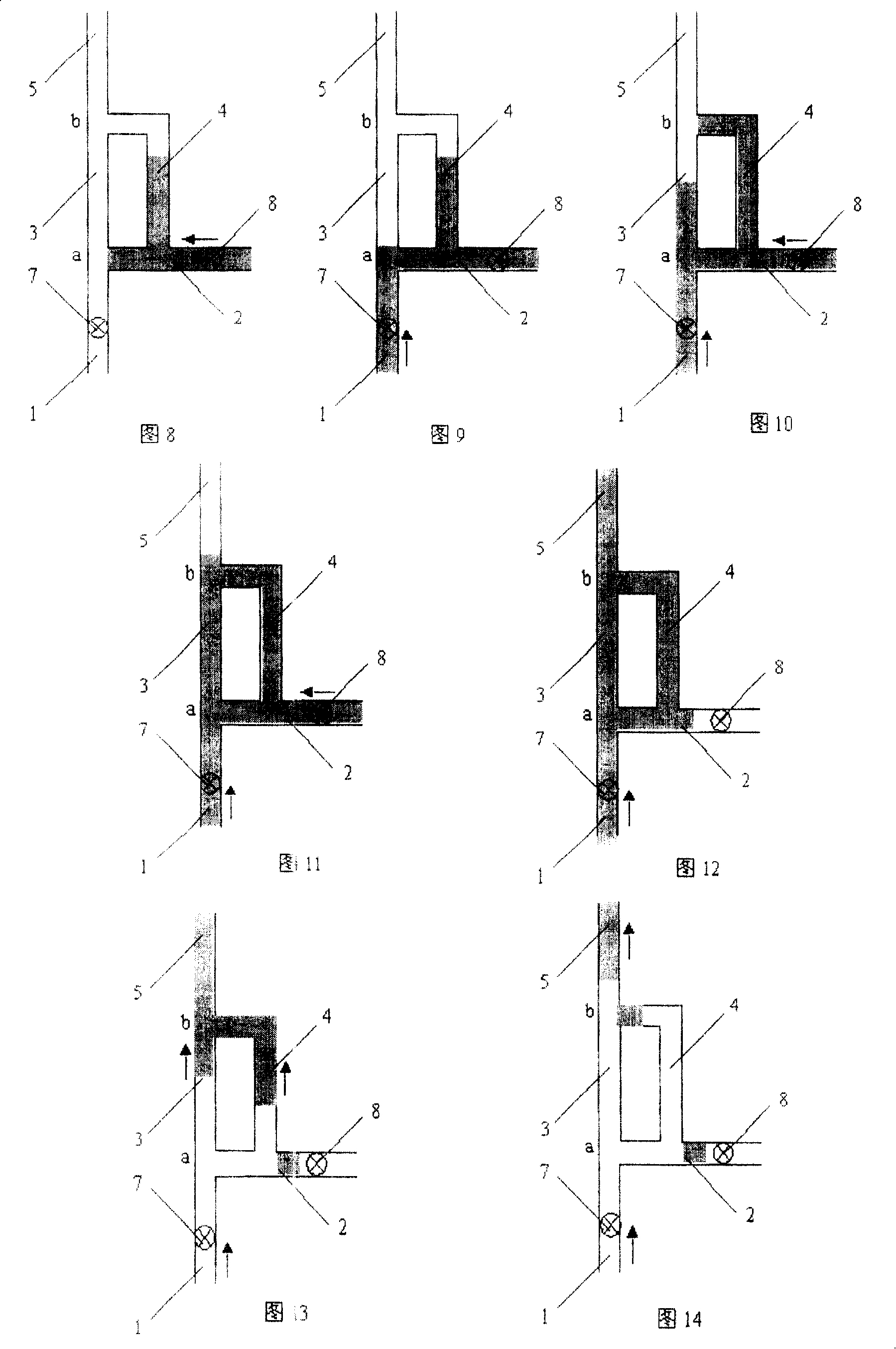
[0038] As shown in FIGS. 8-14 , for an asymmetrical double confluence flow path, the purpose of not needing to distinguish the order of liquids can be achieved by setting two sensors. For example, a sensor 7 is arranged upstream of the main micropipe 1 near the confluence a, and another sensor 8 is arranged upstream near the branch of the auxiliary pipe 2 . As shown in Figure 8, assuming that the first stream of liquid flows along the auxiliary microchannel 2 to the double confluence structure, then when the sensor 8 detects its liquid head, it can continue to drive the liquid to flow through the bifurcation through an appropriate delay until it successively passes through the bifurcation. Somewhere in the confluence a and the bypass micropipe 4 stops (as shown in FIG. 9 ). Then drive the second common liquid in the main microchannel 1, and when the sensor 7 detects its liquid head, also continue to drive the liquid to flow through the confluence a through an appropriate time ...
Embodiment 3
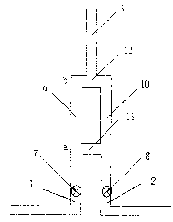
[0041] Such as Figure 15 As shown, the present embodiment provides a symmetrical double confluence flow path, which includes two symmetrical parallel micro-pipes 9, 10, and a micro-pipe 11 is connected to the middle of the two micro-pipes 9, 10 to form The first confluence a, the downstream of two micropipes 9, 10 forms the second confluence b by another micropipe 12, the common downstream pipeline 5 is connected to branch micropipe 12 central parts, at the first confluence a two micropipes A sensor 7, 8 is respectively arranged upstream of them. In this embodiment, the two micropipes 9 and 10 downstream of the confluence a are equivalent to a downstream micropipe and a bypass micropipe in terms of working principle. Since they are arranged symmetrically, they are mutually downstream micropipes and bypass micropipes. through microchannels.
[0042] This symmetrical flow path arrangement no longer distinguishes the first and second liquids, as long as any one of them flows f...
PUM
 Abstract
Description
Claims
Application Information
 - R&D Engineer
- R&D Manager
- IP Professional
- Industry Leading Data Capabilities
- Powerful AI technology
- Patent DNA Extraction
Browse by: Latest US Patents, China's latest patents, Technical Efficacy Thesaurus, Application Domain, Technology Topic, Popular Technical Reports.
© 2024 PatSnap. All rights reserved.Legal|Privacy policy|Modern Slavery Act Transparency Statement|Sitemap|About US| Contact US: help@patsnap.com