
Protection insulating type change-over switch

A technology of protection isolation and transfer switch, applied in the direction of electrical switches, electrical components, circuits, etc., can solve the problems of switch burning, affecting the quality of the switch, hidden safety hazards in the use process, etc., to improve the overall quality and avoid damage.

Inactive Publication Date: 2008-05-14
SHANGHAI PUHE TECH
View PDF5 Cites 0 Cited by
  • Summary
  • Abstract
  • Description
  • Claims
  • Application Information

AI Technical Summary

Problems solved by technology

[0002] At this stage, the universal transfer switch used in various environments and conditions has no isolation device inside the switch, and arcs and sparks are prone to occur between the contacts of the switch. After the switch internally catches fire, the switch is burned as a whole, which not only affects the quality of the switch, but also There are safety hazards during use

Method used


Image

  • Protection insulating type change-over switch

Examples


Embodiment Construction

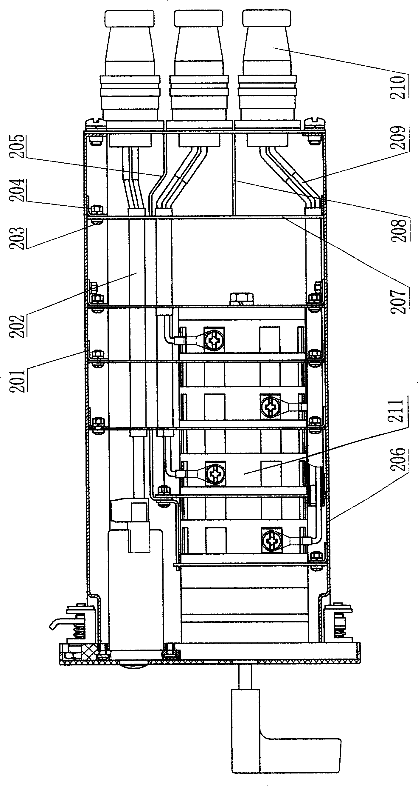
[0011] According to the drawings, a protective isolation switch includes a set of contact bases 211 inside the housing 206, one end is connected to the contact base 211, the other end is connected to the aviation connector 210, and an isolation metal sleeve is covered. The wire 209 of the pipe 202; the protective isolation plate 207 is set on the contact base 211 and is located at the junction of each adjacent contact base, and is fixed on the inner wall of the housing 206 through the bent plate 201 with screws 203 and nuts 204 Above: the protective isolation curved plate 205 and the protective isolation horizontal plate 208 are respectively set between the three groups of wires connected to the aviation connector 210 through the protective isolation plate 207 .


PUM


Abstract

The invention discloses a protective isolation switch, which comprises a shell, a contact base with head and tail engagement, an aviation connector, some wires, and protective isolation plates arranged on contact base. This invention solves the problems during using switch, such as electric arc, spark, damage to whole switch, and other hidden danger on security.

Description

technical field [0001] The invention relates to a transfer switch. Background technique [0002] At this stage, the universal transfer switch used in various environments and conditions has no isolation device inside the switch, and arcs and sparks are prone to occur between the contacts of the switch. After the switch internally catches fire, the switch is burned as a whole, which not only affects the quality of the switch, but also There are potential safety hazards during use. Contents of the invention [0003] The technical problem to be solved by the present invention is to provide a protective isolation switch that overcomes the above-mentioned shortcomings and improves safety. [0004] The present invention is achieved in the following way: a protective isolation switch, including a housing, a set of end-to-end contact bases, aviation connectors and wires connecting the contact bases and aviation connectors, and also includes a set of A protective barrier on the c...

Claims


Application Information

Patent Timeline
Patent Type & Authority Patents(China)
IPC IPC(8): H01H19/04H01H19/08
Inventor 陈小萍
Owner SHANGHAI PUHE TECH
Learn More