Luggage carrier mounting structure for motor-bicycle

A technology for a motor two-wheeled vehicle and a luggage rack, which is applied to luggage racks, bicycle accessories, bicycle saddles, etc., can solve the problems of reduced appearance, obstruction of the luggage rack 6, wear of the rear half of the long seat 1, etc. Appearance, life extension, and compactness

Inactive Publication Date: 2008-03-26
HONDA MOTOR CO LTD
View PDF7 Cites 1 Cited by
  • Summary
  • Abstract
  • Description
  • Claims
  • Application Information

AI Technical Summary

Problems solved by technology

[0005] However, although the buffer sheet 8 is installed, when the luggage is placed on the luggage rack 6 and travels, the buffer sheet 8 contacts and rubs against the rear half of the long seat 1, so the rear half of the long seat 1 is worn.
As a result, the life of the long seat 1 and the shock absorber 8 is shortened
[0006] In addition, when traveling without luggage, if the stay 5 and the luggage rack 6 are permanently installed behind the single seat 1, the appearance will be reduced.
[0007] In addition, when someone rides on the second half of the single seat 1, the buffer sheet 8 and the luggage rack 6 shown in the solid line will often get in the way

Method used


Image

  • Luggage carrier mounting structure for motor-bicycle
  • Luggage carrier mounting structure for motor-bicycle
  • Luggage carrier mounting structure for motor-bicycle

Examples


Embodiment Construction

[0055] Hereinafter, the best mode for carrying out the present invention will be described with reference to the drawings. Furthermore, the drawings are viewed according to the directions marked in the drawings. In addition, in the description, front and rear and left and right refer to directions seen from the occupant.

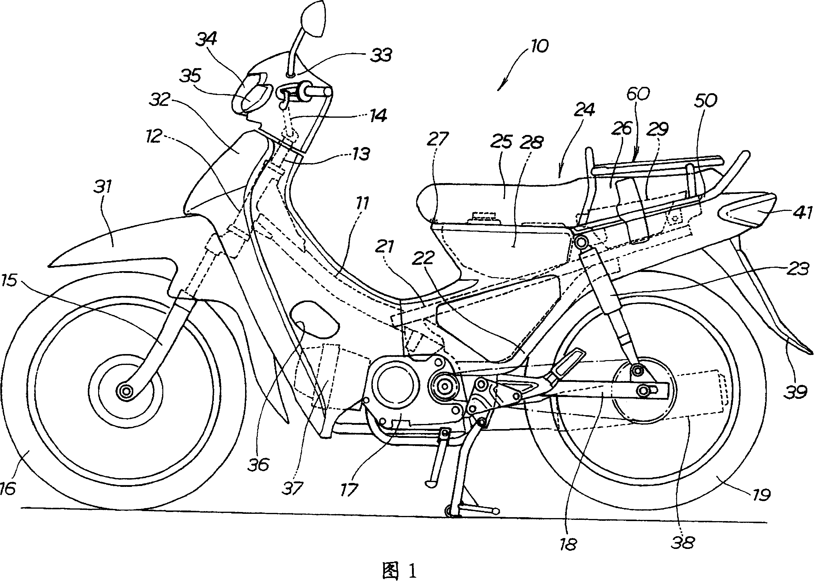
[0056] Fig. 1 is a side view of the two-wheeled motor vehicle of the present invention. The two-wheeled motor vehicle 10 has the following structure: a head pipe 12 is installed at the front end of the main frame 11, a steering shaft 13 is rotatably inserted through the head pipe 12, and a steering handlebar is installed on the upper end of the steering shaft 13. 14. A front fork 15 is provided on the lower part of the steering shaft 13, and the front wheel 16 is mounted on the front fork 15 and can rotate freely. Engine 17 is arranged at the rear portion lower portion of main frame 11, and swing arm 18 stretches out from the rear portion of main frame 11,...


PUM


Abstract

To provide a cargo bed mounting structure of a motorcycle having excellent appearance of a rear part of a motorcycle body without shortening the lifetime of a seat. Leg members 63L and 63R are mounted on a grab rail 50, and the length of the leg members is set so as to ensure a space d between a lower side of a cargo loading part 61 and a rear seat 26 for a pillion passenger. Since the space d between the lower side of the cargo loading part 61 and the rear seat 26 for the pillion passenger is ensured, a carrier 60 is not brought into contact with the rear seat 26 for the pillion passenger, and the lifetime of the rear seat 26 for the pillion passenger can be prolonged. The carrier 60 is detachably engaged with the grab rail 50. When the pillion passenger is seated on the rear seat 26 for the pillion passenger, the carrier 60 is detached. As a result, only the grab rail 50 is arranged, and excellent appearance of a motorcycle can be maintained.

Description

technical field [0001] The invention relates to an improved luggage rack installation structure of a two-wheeled motor vehicle. Background technique [0002] It is known that a rear passenger seat of a two-wheeled motor vehicle is provided with a luggage rack that can be freely erected and swiveled (for example, refer to Japanese Patent Laid-Open No. 60-87783 (FIG. 1)). [0003] The technique disclosed in Japanese Utility Model Application Laid-Open No. 60-87783 will be described with reference to the following drawings. [0004] Fig. 19 is a diagram illustrating the basic construction of the prior art. 1 is a long seat, 2 is a fuel tank, 3 is a rear wheel, 4 is a seat rail, 5 is a strut, 6 is a luggage rack, 7 is a hinge, and 8 is a buffer sheet. When not taking people on the second half of the long seat 1 (rear passenger seat), the luggage rack 6 represented by the solid line is put down at the position of the double-dot dash line, and like this, the luggage can be place...

Claims


Application Information

Patent Timeline
IPC IPC(8): B62J7/04B62J1/28
CPCB62J7/04B62J11/00
Inventor 井之川浩志原宏和松蓬·萨瑞差瑞塔纳考那特瓦特·幸帕辛哈卡荣·恰帕蒂
Owner HONDA MOTOR CO LTD
Why Eureka
Try Eureka