Method for adjusting the level of optical signals

A technology of signal power level and power level, which is applied in lasers, laser components, and lasers using scattering effects, etc., can solve problems such as faulty pulses and cannot be quickly balanced, and achieve good noise performance.

Inactive Publication Date: 2008-01-30
NOKIA SIEMENS NETWORKS GMBH & CO KG
View PDF3 Cites 0 Cited by
  • Summary
  • Abstract
  • Description
  • Claims
  • Application Information

AI Technical Summary

Problems solved by technology

The receiver's automatic amplification adjustments are generally not able to quickly balance this power level fluctuation, and the result is a glitch pulse on the order of nanoseconds

Method used


Image

  • Method for adjusting the level of optical signals
  • Method for adjusting the level of optical signals
  • Method for adjusting the level of optical signals

Examples


Embodiment Construction

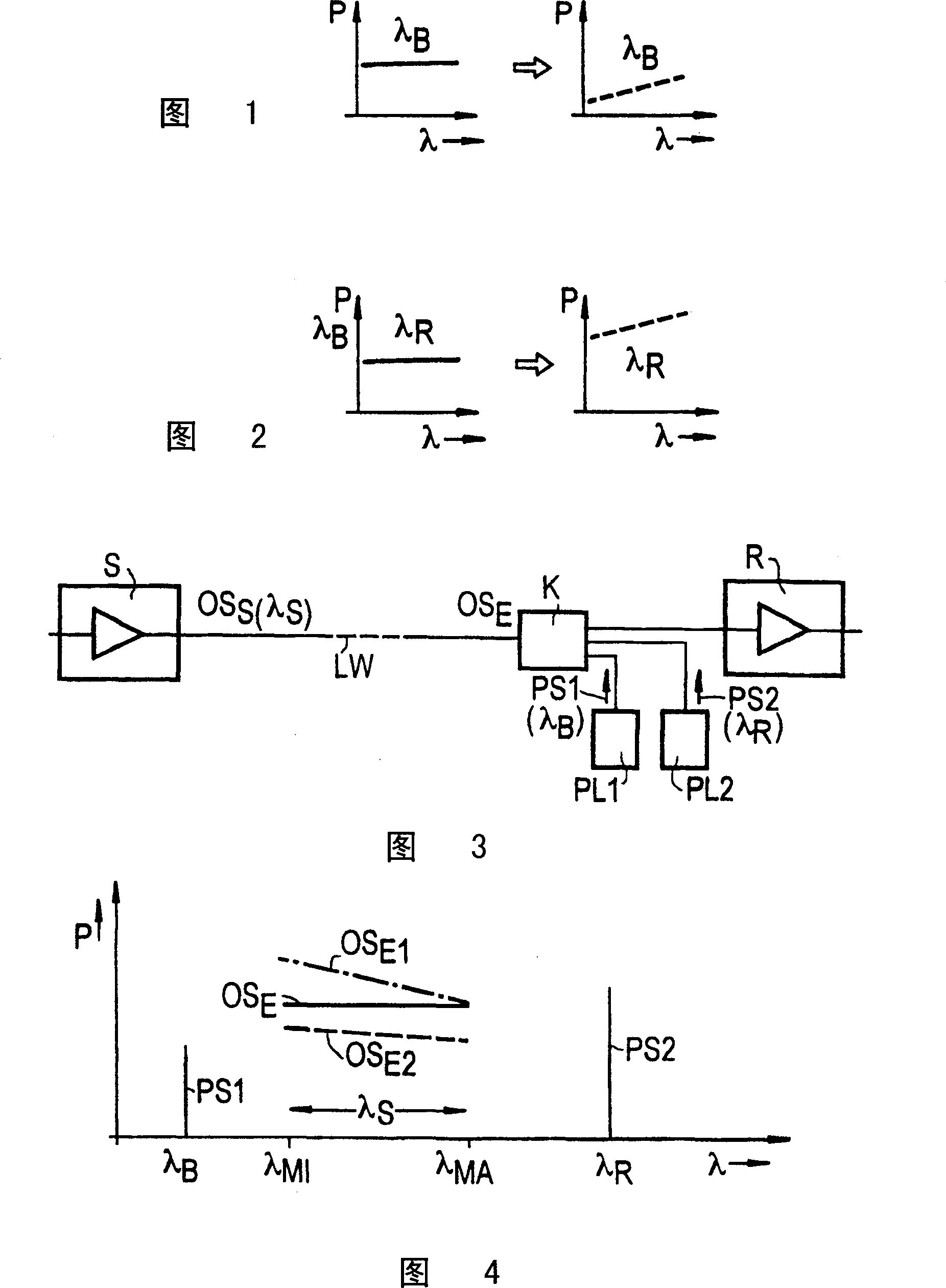
[0040] Accompanying drawing 3 shows that the transmission section has a transmitting device S, such as a laser or an amplifier, which will have a relatively large wavelength range λ s optical signal OS s Feeds into the optical waveguide LW and has a receiver R which also has an amplifier. For example, an optical signal may involve a digital multiplexed signal with relatively large bandwidth or a wavelength multiplexed signal. The optical signal (received signal) OS that will be damped due to the transmission section E Input to the receiving device R.

[0041] Two pump lasers PL1 and PL2 are installed at the receiver, and the pump laser will be located at the minimum wavelength λ of the optical signal MI The following wavelength is λ B The pump signal PS1, and will be located at the optical signal maximum wavelength λ MA The above wavelength is λ R The pumping signal PS2 (Fig. 2) is fed into the optical waveguide through the coupler K. The pump signal PS2 makes the optic...


PUM


Abstract

Pump energy with a wavelength which is below the wavelength of an optical signal is fed into a transmission section from a pump laser via a coupler. The received optical signal is attenuated with increasing pump power with signals having higher frequencies being more strongly damped.

Description

technical field [0001] The present invention relates to methods of tilting and power level adjustment of optical signals. Background technique [0002] Optical signals are transmitted through optical waveguides. Fiber amplifiers are often used for their reinforcement. Such fiber amplifiers use either specially metered fiber sections or nonlinear effects on normal transmission fibers, such as the fiber-Raman-amplifier described in ntz, vol. 43, (1990) vol. 1, pp. 8-13 . [0003] Damping links are also used in many transmission devices to adjust the required power level value, such as the input power level of the amplifier, which is for example in IEEE Photonic Technology, Volume 6, Volume 4, April 1994, 509 to page 512. [0004] Modern transmission systems transmit multiple signals by means of the wavelength multiplexing method, WDM, in which separate multiple transmission channels are combined into one transmission band, which are amplified together and have an influence...

Claims


Application Information

Patent Timeline
Patent Type & Authority Patents(China)
IPC IPC(8): H04B10/17H01S3/30H04B10/291H04B10/297
CPCH04B10/2971H01S3/302H04B10/2916
Inventor E·戈特瓦德
Owner NOKIA SIEMENS NETWORKS GMBH & CO KG
Why Eureka
Try Eureka