Electromagnetic drive for switching devices

An electromagnetic drive and switch technology, applied in the direction of electromagnets, electric switches, movable winding electromagnets, etc., can solve the problems of the load effect of the installation space, and achieve the effect of prolonging the service life and reducing maintenance difficulties.

Inactive Publication Date: 2008-01-23
SIEMENS AG
View PDF4 Cites 0 Cited by
  • Summary
  • Abstract
  • Description
  • Claims
  • Application Information

AI Technical Summary

Problems solved by technology

Reluctance drives are generally distinguished by their robust end positions, but they also have the disadvantage that their path and force characteristic curves are non-linear, which are either difficult to change by influences, or have a negative impact on the holding force load or on the end positions. Influences the load on the installation space

Method used


Image

  • Electromagnetic drive for switching devices
  • Electromagnetic drive for switching devices

Examples


Embodiment Construction

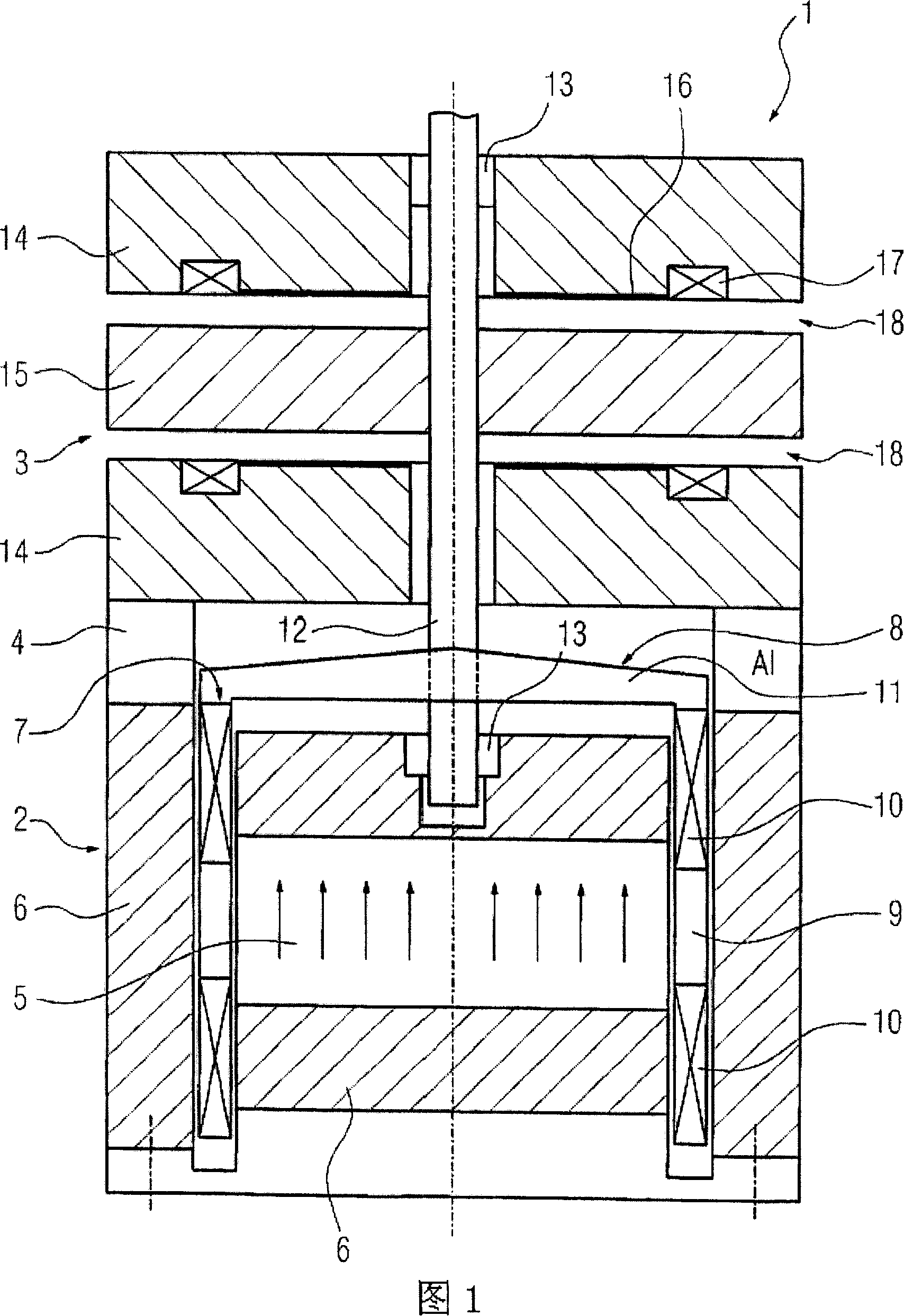
[0022] Fig. 1 illustrates an electromagnetic drive device 1 according to an embodiment of the invention in the form of a sectional view. The electromagnetic driving device 1 includes a driving unit 2 and a locking unit 3 , both of which are connected to each other through an insulating medium composed of a ring-shaped aluminum block 4 . The insulating medium is used to isolate the magnetic field in the driving unit 2 and the magnetic field in the locking unit 3 from each other.

[0023] The drive unit 2 contains a magnetic conductor. The magnetic conductor is composed of a driving magnet 5 capable of generating a driving permanent magnetic field and a soft magnetic yoke 6 fixedly connected with the driving magnet 5 . There is an annular gap 7 in the drive magnet 5 and the yoke 6 , and a part of the armature 8 extends into the annular gap 7 . The armature 8 has a bucket-shaped bobbin 9 made of insulating material and a coil of a conductor is wound on a tubular section of the ...


PUM


Abstract

The invention relates to an electromagnetic drive (1) for a switching device, especially a medium-voltage switching device, comprising a drive unit (2) consisting of a magnet body (5), an armature (8) which is at least partially moveably arranged therein, at least one drive magnet (5) producing a permanent magnetic drive field and at least one conductor (10) extending at least partially inside said magnetic drive field. A locking unit (3) is provided in order lock the armature (8) in at least one end position. In order to provide an electromagnetic drive which can be fixed in an end position in a simple manner, ensuring simple control thereof, the locking unit (3) comprises at least one soft magnetic moving part (15) which is firmly connected to the armature (8) and which bridges an air gap (18) for a permanent magnetic locking field in the end position of the armature (8), whereby the magnetic locking field is produced independently from the magnetic driving field by at least one locking magnet (16) which is associated with a pull-off coil (17) through which current can flow independently of the conductor in order to pull the armature out of its end position.

Description

technical field [0001] The invention relates to an electromagnetic driving device for a switch, in particular to an electromagnetic driving device for a switch applied in the technical field of medium voltage. The electromagnetic drive device has a drive unit comprising a magnetic conductor with at least one drive magnet capable of generating a permanent magnetic field, an armature at least partially movably placed in the magnetic conductor, and at least one at least partially The ground extends to the conductor in the driving magnetic field; wherein, there is also a locking unit that locks the armature in at least one end position. Background technique [0002] Such an electromagnetic drive is known, for example, from DE 198 15 538 A1. The driving device disclosed therein has a three-phase AC linear motor composed of a plurality of motor modules assembled together. The motor module consists of a number of fixed motor coils and associated moving parts moving longitudinally...

Claims


Application Information

Patent Timeline
IPC IPC(8): H01H53/01H01F7/06H01H53/015
CPCH01H33/6662H01F7/066H01H53/015
Inventor 彼得-克劳斯·布迪克拉尔夫·沃纳
Owner SIEMENS AG
Why Eureka
Try Eureka