Pneumatic apparatus controlling method and pneumatic apparatus
A control method and equipment technology, applied in the control of wind turbines, mechanical equipment, wind turbines, etc., can solve problems such as rotor cabin and/or tower damage, and achieve the effects of increasing load, reducing damage, and increasing wind resistance
- Summary
- Abstract
- Description
- Claims
- Application Information
AI Technical Summary
Problems solved by technology
Method used
Image
Examples
Embodiment Construction
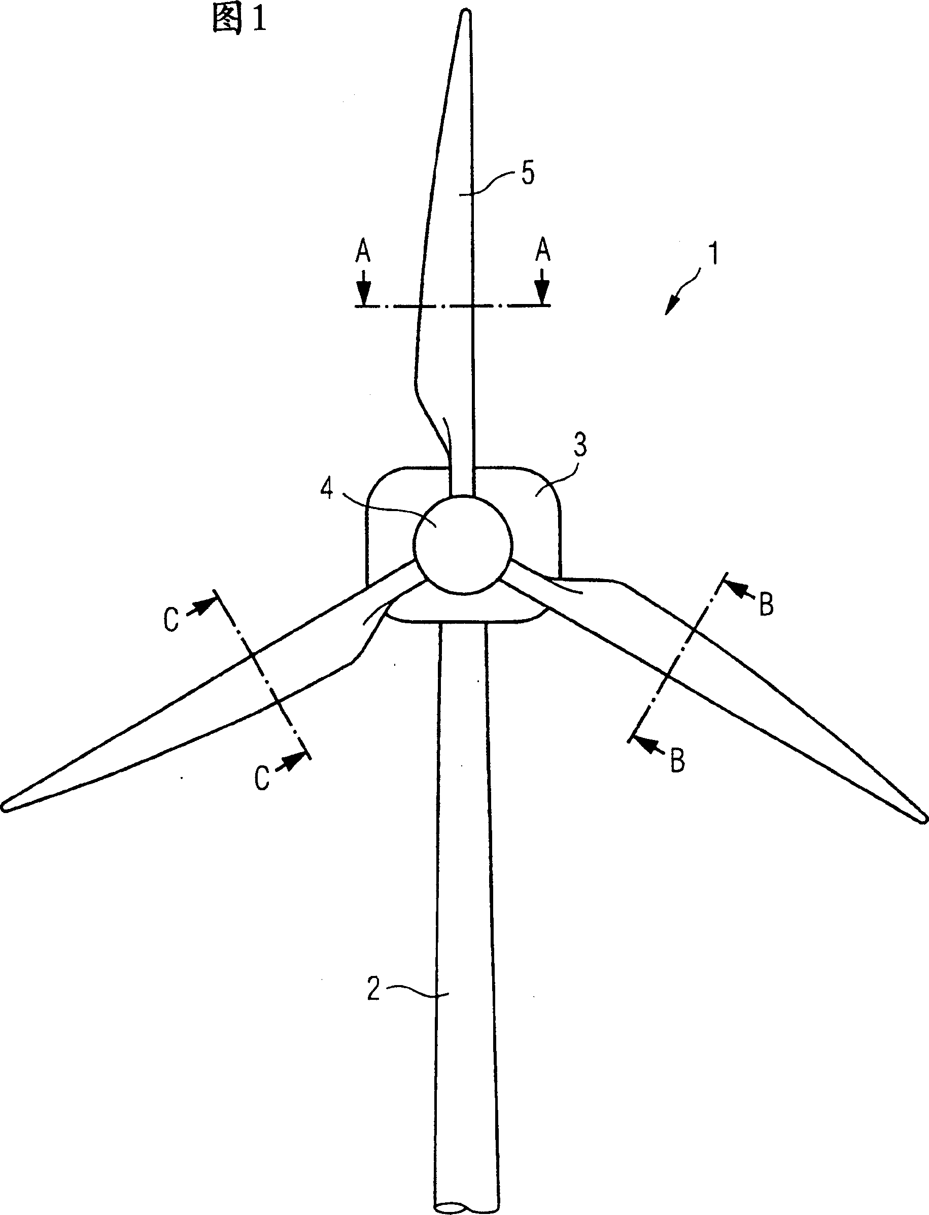
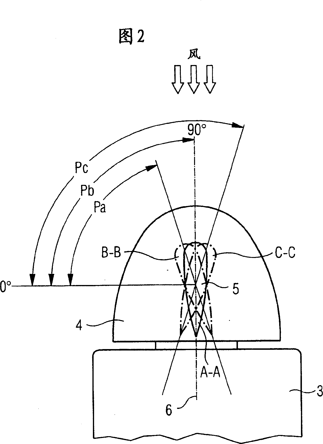
[0028] FIG. 1 is a front view of a wind turbine 1 . Three rotor blades 5 are designed on a rotor blade plane around a rotor hub 4 mounted on the wind turbine chamber or nacelle 3 . The included angle between every two adjacent rotor blades is equal, in the example shown the included angle is 120 degrees. Lines A-A, B-B, C-C represent top views along the rotor blade axis. These figures are reproduced in Figure 2, which represents a top view of a wind turbine tower. The turbine rotor shaft 6 rotates in a direction perpendicular to the rotor blade plane on which the rotor blades are mounted. The rotor hub 4 is seated on the nacelle 3 and is rotatable. On top of the rotor hub 4 can be seen a cross section of all three rotor blades designed along A-A, B-B, C-C. Each sectional view represents the state at the moment when the corresponding rotor blade reaches its top position.
[0029] In the rotor blade stop position of the invention shown in Figure 2, the rotor blades A-A are ...
PUM
 Abstract
Description
Claims
Application Information
 - R&D
- Intellectual Property
- Life Sciences
- Materials
- Tech Scout
- Unparalleled Data Quality
- Higher Quality Content
- 60% Fewer Hallucinations
Browse by: Latest US Patents, China's latest patents, Technical Efficacy Thesaurus, Application Domain, Technology Topic, Popular Technical Reports.
© 2025 PatSnap. All rights reserved.Legal|Privacy policy|Modern Slavery Act Transparency Statement|Sitemap|About US| Contact US: help@patsnap.com


