Method for compressive shrinking and rubber blanket shrinking system

A rubber blanket, mechanical compression technology, applied in the direction of adding compressed water, textile and papermaking, fabric surface trimming, etc., can solve problems such as cooling rubber blankets

Inactive Publication Date: 2007-09-05
A MONFORTS TEXTILMASCHINEN GMBH & CO KG
View PDF3 Cites 1 Cited by
  • Summary
  • Abstract
  • Description
  • Claims
  • Application Information

AI Technical Summary

Problems solved by technology

However, in order to overcome this problem, one cannot cool the rubber blanket more strongly, because the rubber blanket that is too cold does not undergo mechanical compression of the fabric web and is shaped according to regulations.

Method used


Image

  • Method for compressive shrinking and rubber blanket shrinking system
  • Method for compressive shrinking and rubber blanket shrinking system
  • Method for compressive shrinking and rubber blanket shrinking system

Examples


Embodiment Construction

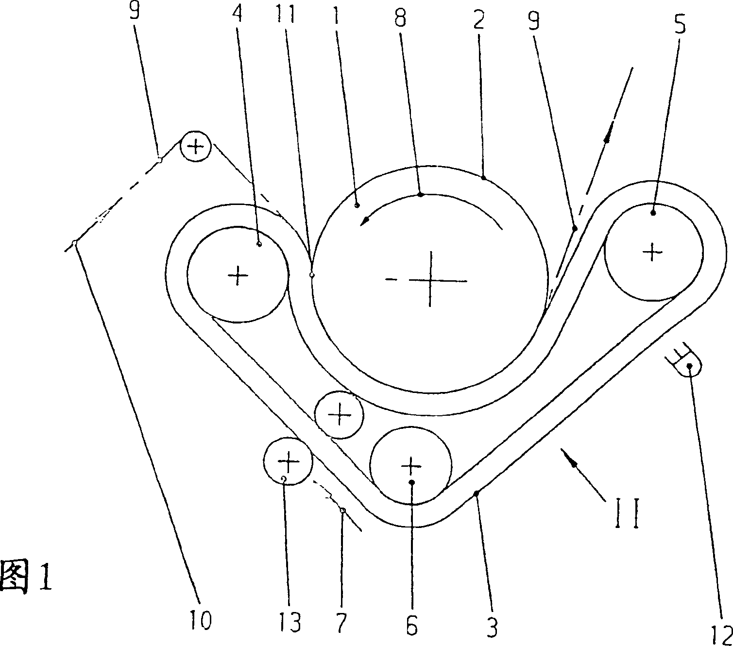
[0024] Figure 1 shows a longitudinal section (perpendicular to the marked roller axis) of a rubber belt shrinking device. The device consists in principle of a heated main drum 1 , onto the peripheral outer surface 2 of the main drum 1 , of a circulating rubber blanket 3 which is tensioned in its longitudinal direction. The rubber blanket 3 is guided in a marked running direction 7 via so-called pressure rollers 4 and guide or deflection rollers 5 , 6 . The corresponding deflection 8 of the main drum 1 is also indicated by an arrow. The textile web 9 to be preshrunk is passed along the indicated conveying direction 10 via the pressure roller 4 into a so-called shrinking nip 11 , where mechanical shrinking takes place.

[0025] The mechanically produced pre-shrinking is effected by the heated main cylinder 1 while the fabric web 9 is shaped by the compression of the fabric web 9 on the peripheral outer surface 2 by means of the rubber blanket 3 . In order to achieve the pre-s...


PUM


Abstract

This plant is used to treat textile webs (9) which do not fully cover the width of the cloth belt (3) and of the cylinder (1). This leaves inactive regions of the belt at its edges, which may be subjected to greater heating. Such regions are separately and more strongly cooled than the active regions (27) of coverage, after lifting-off the main cylinder. An Independent claim is included for the corresponding pre-shrinkage plant for textiles.

Description

technical field [0001] The invention relates to a method for mechanically shrinking a web of textile fabric by means of a mechanical or rubber blanket shrinking device, wherein the mechanically compressed fabric web is passed between a circulating rubber blanket and a heated main or heating roll Stretching takes place between the circumferential surfaces and cooling is performed each time the rubber blanket exits the main drum. The invention also relates to a rubber blanket pre-shrinking device in which a mechanically compressed fabric web is sizing between a circulating rubber blanket and the circumferential surface of a heated main roller, and each slave main roller of the rubber blanket Coolant is dispensed in the upper exit area. Rubber blankets are also called rubber belts or rubber interlinings. Background technique [0002] A blanket shrinking plant comprising a so-called blanket calender is described in DE-AS 10 72 220 . The main cylinder of the mechanical shrinki...

Claims


Application Information

Patent Timeline
Patent Type & Authority Patents(China)
IPC IPC(8): D06C21/00
CPCD06C21/00
Inventor E·克拉斯H·霍彭施托克P·施密茨
Owner A MONFORTS TEXTILMASCHINEN GMBH & CO KG
Why Eureka
Try Eureka