Modified concentric spectrograph

a spectrograph and concentric technology, applied in the field of diffraction-grating spectrographs, can solve the problems of inability to measure the intensity of the desired spectrum independently from the undesired spectrum, the sharp image of the concentrated spectrograph, and the difficulty of preventing the contamination of stray light by the concentric spectrograph

Inactive Publication Date: 2011-10-11
HORIBA INSTR
View PDF23 Cites 2 Cited by
  • Summary
  • Abstract
  • Description
  • Claims
  • Application Information

AI Technical Summary

Benefits of technology

[0012]It is an object of this invention to provide a modified concentric spectrograph for dispersing polychromatic light with increased stray light rejection at the exit port.
[0014]It is another object of this invention to provide a modified concentric spectrograph which is compact, relatively inexpensive to manufacture, and relatively immune to miscalibration.
[0016]It is yet another object of this invention to provide an improved concentric spectrograph that can be constructed with conventional optical components.

Problems solved by technology

First, concentric spectrographs form sharp images due to the inherent absence of Seidel aberrations.
First, concentric spectrographs have difficulty preventing stray light from contaminating with the desired spectrum at the exit port of the spectrograph.
Therefore, the intensity of the desired spectrum cannot be measured independently from the undesired spectrum.
Filtering, however, only works when the stray light has a different quality than the desired light, such as a different wavelength or polarization.
When the wavelengths of the stray and spectral light are the same, conventional wavelength filtering techniques will not work.
In any case, filtering reduces the intensity of the desired spectrum, which reduces the throughput of the spectrograph.
Another common disadvantage of conventional concentric spectrographs is their relatively large F-numbers.
When the F-number of a spectrograph is large, the solid angle in which light can enter the spectrograph is relatively small, which limits the throughput of the spectrograph.
Also, spectrometers having large F-numbers require relatively long focal lengths, which make the instrument large.

Method used


Image

  • Modified concentric spectrograph
  • Modified concentric spectrograph
  • Modified concentric spectrograph

Examples


Embodiment Construction

[0034]According to the present invention, a method and apparatus for diffracting polychromatic light using a modified concentric spectrograph are provided. By means of this invention, polychromatic light is diffracted and imaged at an exit port with high resolution and increased stray light rejection.

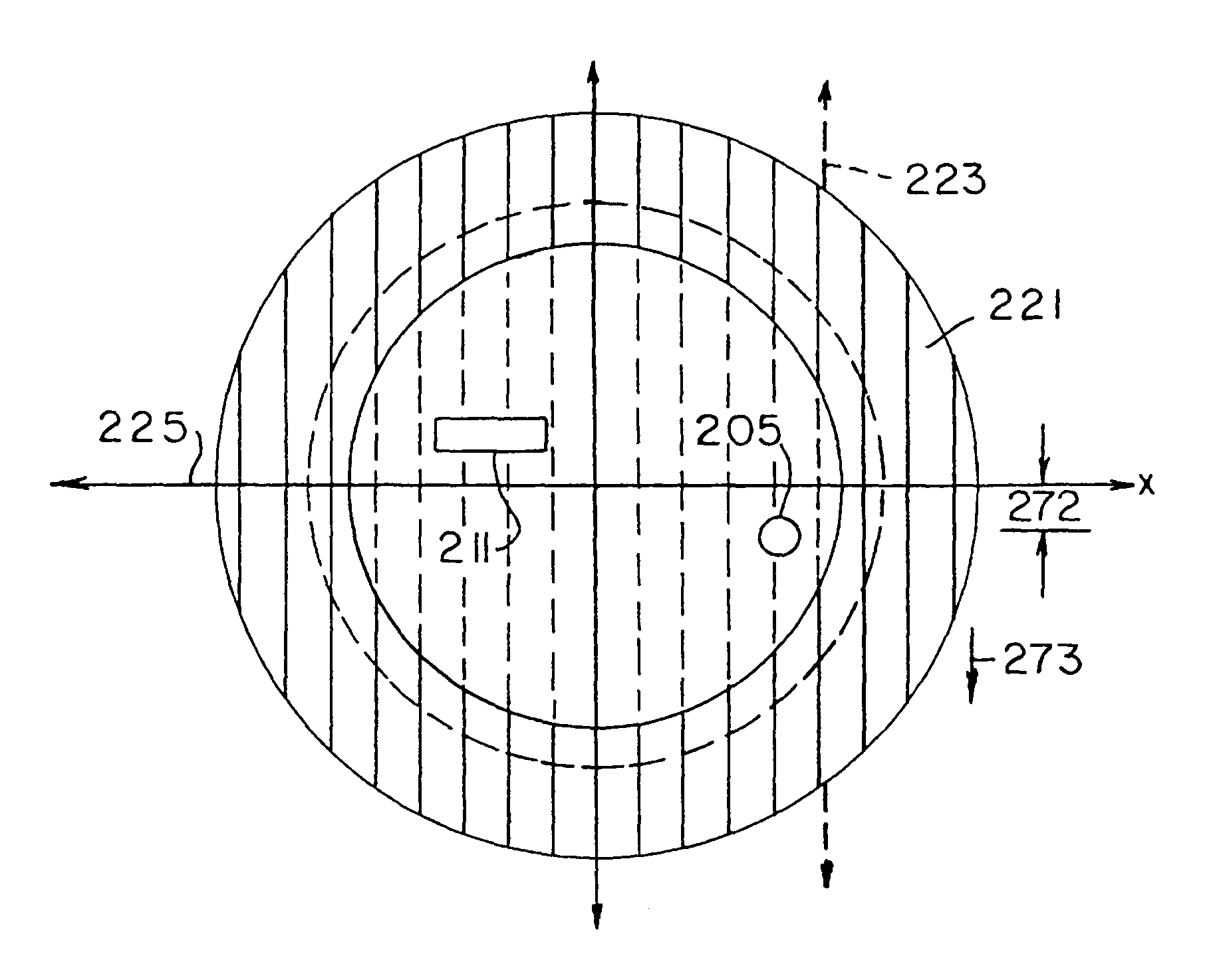
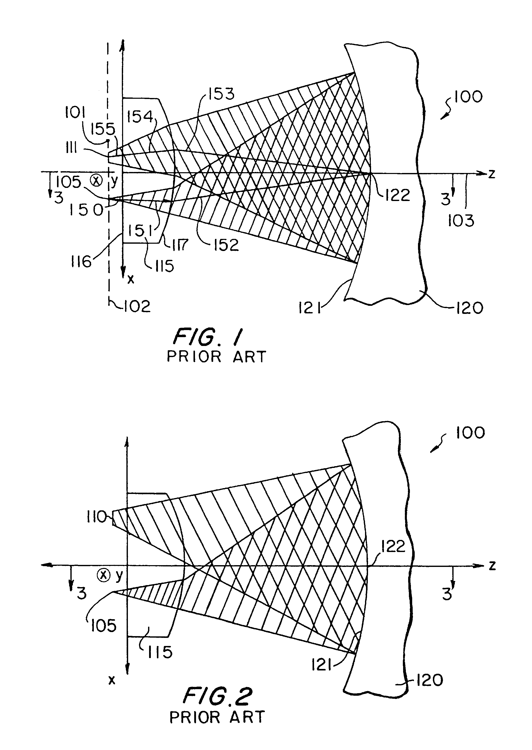
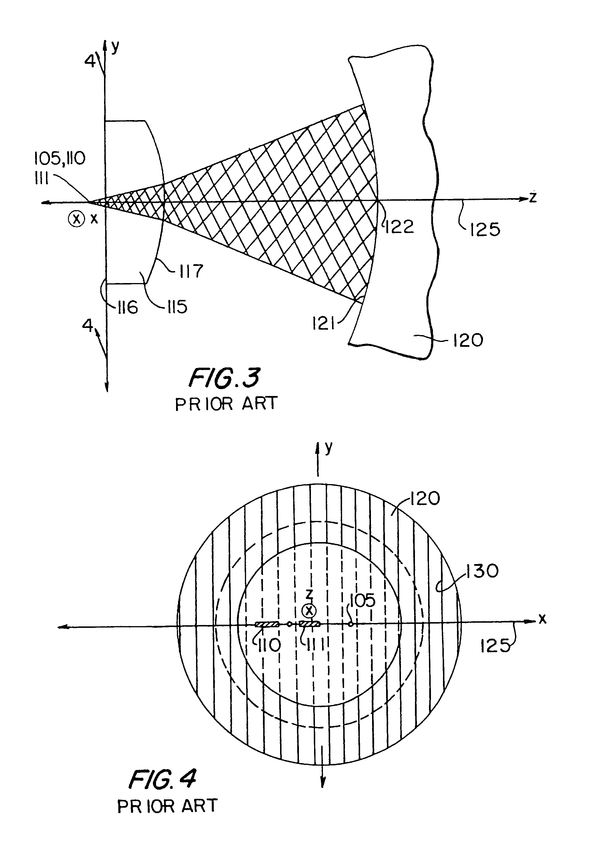
[0035]Conventional concentric spectrographs include an entrance port, an exit port, a hemispherical lens, and a concave diffraction grating, which has a meridian plane. In operation, a beam of light enters the spectrograph through the entrance port and propagates substantially in and along the meridian plane until the diffracted light exits the spectrograph at the exit port. Therefore, the entrance and exit ports are positioned substantially in the meridian plane.

[0036]This arrangement, however, has the important disadvantage of contaminating the desired spectrum at the exit port with stray light due to internal reflections of other spectra. For example, conventional concentric spectrog...


PUM


Abstract

A modified concentric spectrograph for diffracting light with high stray light rejection without astigmatism is provided. The modified spectrograph includes a grating, a lens, and at least one entrance port and one exit port. The grating has a concave surface and a meridian plane with a first side and a second side. The lens has a substantially planar surface and a convex surface. Preferably, the convex and concave surfaces are substantially concentric. The ports are substantially located on different sides of the meridian plane near a focal plane of the spectrograph. The position of a focal plane may be modified using an optically transmissive triangular prism with a reflective surface, and an optically transmissive block. The position of a focal plane may further be modified with one or more optically transmissive plates. Methods for using the spectrograph are also provided.

Description

CROSS REFERENCE TO RELATED APPLICATION[0001]This claims the benefit of U.S. provisional application No. 60 / 039,207, filed Feb. 28, 1997.BACKGROUND OF THE INVENTION[0002]This invention relates to diffraction-grating spectrographs. More particularly, this invention relates to concentric diffraction-grating spectrographs with modified arrangements of their optical components.[0003]An optical spectrograph collects light at its entrance slit and forms an image of the entrance slit in the exit plane at the wavelengths present in the light source. Diffraction-grating spectrographs use one or more diffraction gratings to diffract light into specific wavelengths and to select a predetermined portion of the wavelengths present in that light.[0004]Concentric spectrographs are particularly well suited for applications requiring sharp spectral and spatial imaging. One type of concentric spectrograph includes an entrance port, an exit port, a hemispheric field lens, and a concave diffraction grat...

Claims


Application Information

Patent Timeline
IPC IPC(8): G01J3/28G01J3/02G01J3/18G02B5/18G02B13/00
CPCG01J3/02G01J3/0208G01J3/0256G01J3/0262G01J3/18
Inventor SLUTTER, WARREN S.JIANG, WUTHEVENON, ALAIN F. R.MILLET, VIVIANE D.GOLDSTONE, JEREMY J.
Owner HORIBA INSTR
Why Eureka
Try Eureka