System and method of automatically calibrating the gain for a distributed wireless communication system

a wireless communication system and automatic calibration technology, applied in the field of wireless communication systems, can solve the problems of system disadvantage, time-consuming and expensive process, and the gain of the receive (and transmit) path is not completely deterministic, and achieve the effect of increasing the gain of the receive path

Inactive Publication Date: 2010-11-16
MIND FUSION LLC
View PDF49 Cites 12 Cited by
  • Summary
  • Abstract
  • Description
  • Claims
  • Application Information

AI Technical Summary

Benefits of technology

[0019]Yet another aspect of the present invention includes a method of maintaining transmit peak power at a constant level regardless of modulation type in an outdoor unit of a time division duplexing wireless communication system, the method comprising providing a control signal at a predetermined time delay after a transition from a receive mode to a transmit mode, measuring the amplitude of a transmit output signal based on the delayed control signal, providing a predetermined transmit output level, comparing the predetermined transmit output level with the amplitude of the transmit output signal, and generating a signal representative of the comparing so as to maintain transmit peak power at a constant level.

Problems solved by technology

However, these systems suffer significant disadvantages because of the time and expense required to lay high capacity communications cables between each office.
This process is time consuming and expensive.
Furthermore, on the base station side of many radio frequency systems, the gain of the receive (and transmit) path is not completely deterministic and not known in advance due mainly to differing amounts of cable length required to connect the roof-top radio and antenna to the indoor equipment.
All of these techniques incur some amount of additional expense and / or complexity in the base station design and / or installation.
Furthermore, the output power stability of the roof-top radio may be directly affected by the gain of the transmitter circuits.

Method used


Image

  • System and method of automatically calibrating the gain for a distributed wireless communication system
  • System and method of automatically calibrating the gain for a distributed wireless communication system
  • System and method of automatically calibrating the gain for a distributed wireless communication system

Examples


first embodiment

[0082]a. First Embodiment

[0083]One of the challenges in point-to-multipoint systems is how to calibrate the receive path gain of the Base Station which receives different signals at different time slots, and thus, account for the varying length cable between the IDU and ODU and other factors. In a first embodiment of cable compensation, a method of automatically calibrating the gain of the IDU in an RF / IF distributed system so as to compensate for cable loss is now presented. In one embodiment, some or all of the received signals are operating in a power control closed loop. In one embodiment, the method and system include a combination of two independent processes or algorithms. The first algorithm is an Automatic Level Control (ALC) algorithm and the second algorithm is an automatic gain calibration. This method and system can eliminate the need for any calibration of the receive path prior to installation of the Base Station.

[0084]Referring to FIG. 5, a Base Station 106 including...

second embodiment

[0092]b. Second Embodiment

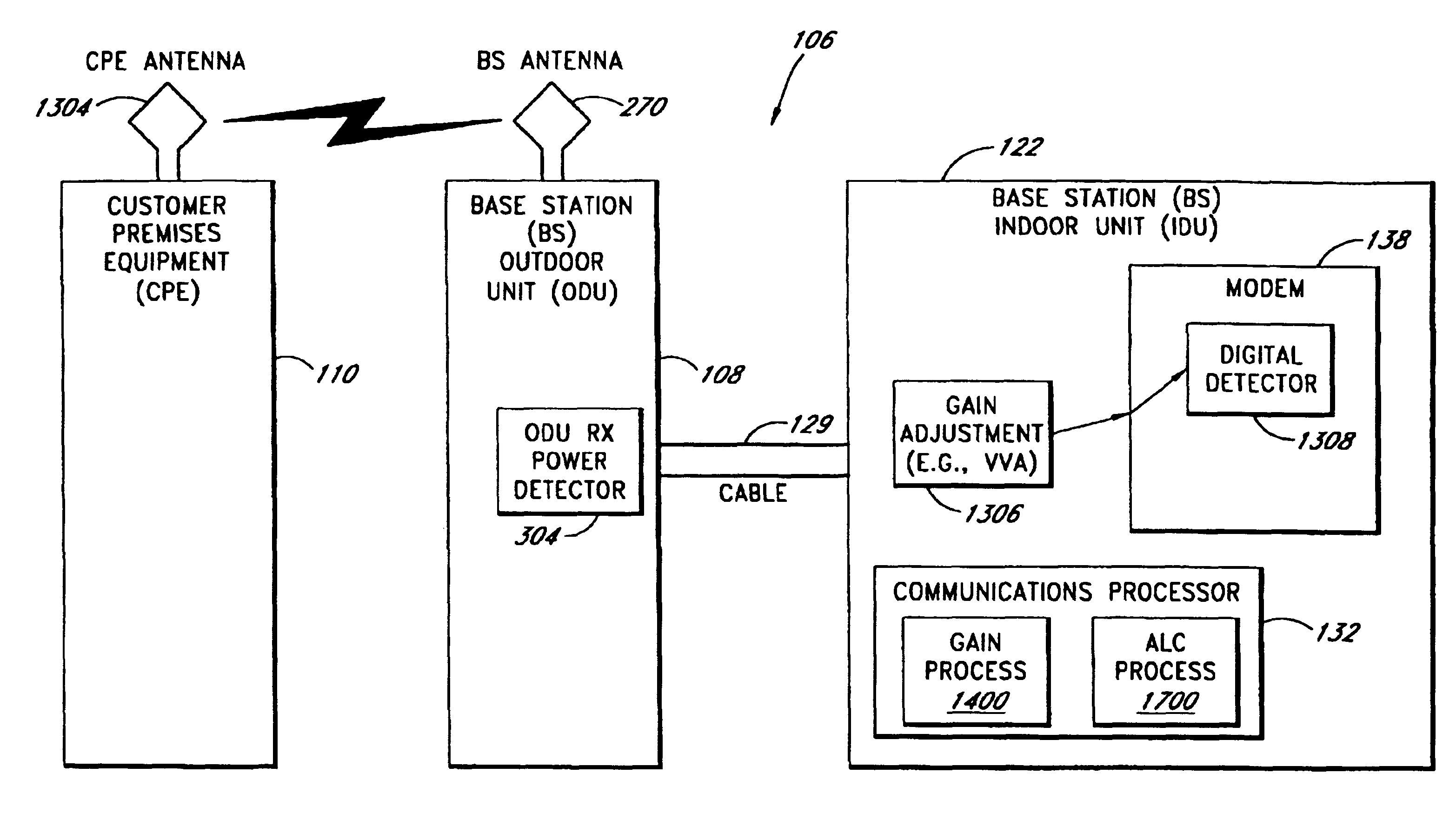
[0093]Referring to FIG. 7, another embodiment of the cable compensation method utilizes Subscriber Equipment or CPE 110′ and the Base Station 106, including the Outdoor Unit 108 (ODU), the Indoor Unit (IDU) 122 and the cable 129 of unknown length, e.g., such as up to or exceeding 1000 feet, connecting them. Only selected components useful for understanding the invention are depicted in this view with a more complete representation of the system having been presented earlier. In one embodiment, the receive gain of the Base Station ODU 108 is calibrated, i.e., the receive gain is known and the output level is known for a known input level. Customer Premises Equipment 110′ (CPE) can have an IDU 122′, a CPE cable 129′ from the IDU 122′ to an ODU 108′ and the CPE antenna 1304. The CPE ODU 108′ includes a variable Tx power component 1510, which may be implemented by one or more of the VVA's 210, 234 and / or 264 of FIG. 4, that feeds the CPE antenna 1304.

[0094]The ...


PUM


Abstract

A system and method providing a wireless broadband connection between base stations and customer sites. The system includes indoor units, within the base stations and customer sites, that communicate across cables to outdoor units. The indoor units link to routers, switches and other devices and services. The outdoor units transmit and receive wireless data and send it to the indoor units. The indoor units control the functioning of the outdoor units by transmitting digital messages along the interface cables. The outdoor units report various detector values to the indoor units, which allows the indoor units to tune and adjust several functions within the outdoor units. Several embodiments for automatically calibrating the receive path gain in the base stations to compensate for the base station cable between the indoor unit and outdoor unit are described. In addition, anAn improved transmit power control technique which is not affected by modulation type, is also described.

Description

[0001]Notice: More than one reissue application has been filed for the reissue of U.S. Pat. No. 6,704,579. The reissue applications are application Ser. Nos. 11 / 372,445 (the present application) and 11 / 496,067. Application Ser. No. 11 / 496,067 claims the benefit of application Ser. Nos. 11 / 372,445(the present application) and is a continuation reissue of U.S. Pat. No. 6,704,579.<?insert-end id="INS-S-00002" ?>BACKGROUND OF THE INVENTION[0002]1. Field of the Invention[0003]Aspects of the present invention generally relate to wireless communication systems. More particularly, embodiments of the present invention relate to a wireless communication system that provides telephone, data and Internet connectivity to a plurality of users.[0004]2. Description of Related Art[0005]Several systems are currently in place for connecting computer users to one another and to the Internet. For example, many companies such as Cisco Systems, provide data routers that route data from personal comp...

Claims


Application Information

Patent Timeline
Patent Type & Authority Patents(United States)
IPC IPC(8): H04Q7/00H04B7/005H04B17/00H04W52/08H04W52/24H04W84/14
CPCH04W52/08H04W52/24H04W52/362H04W52/367H04W84/14H04B17/318
Inventor WOODHEAD, DAVIDSPINAR, BRIANGAZELLE, DAVIDGILBERT, SHELDON
Owner MIND FUSION LLC
Why Eureka
Try Eureka