Method of filtering an image

a filtering method and image technology, applied in the field of filtering an image decoder, can solve the problems of reducing the block effect removal, requiring a large amount of processing time, and all methods have problems, so as to reduce the block and ring effect, enhance the picture quality of the reconstructed image, and maintain the details of the image

Inactive Publication Date: 2008-03-25
LG ELECTRONICS INC
View PDF27 Cites 12 Cited by
  • Summary
  • Abstract
  • Description
  • Claims
  • Application Information

AI Technical Summary

Benefits of technology

[0013]An object of the present invention is to reduce the block and ring effects while maintaining the details of an image. Thus, the object of the present invention is to enhance the picture quality of a reconstructed imaged obtained by decoding a coded bit stream.
[0014]Another object of the present invention is to remove the block and ring effects in a compression-coded image.
[0015]A further object of the present invention is to remove the block and ring effects in a compression-coded imaged coded at a very low bit rate.
[0016]A still further object of the present invention is to remove the block / ring effects in a compression-coded image which is transmitted by a block-by-block basis.

Problems solved by technology

However, these methods all have problems.
Controlling a filtering level only changes pixel values at boundaries between adjacent blocks, resulting in a degradation in the block effect removal.
The projection method requirerequires a large amount of processing time and the filtering based upon the quantization noise is inefficient because additional information must be obtained from the coder, which increases the amount of bits being generated.

Method used


Image

  • Method of filtering an image
  • Method of filtering an image
  • Method of filtering an image

Examples


Embodiment Construction

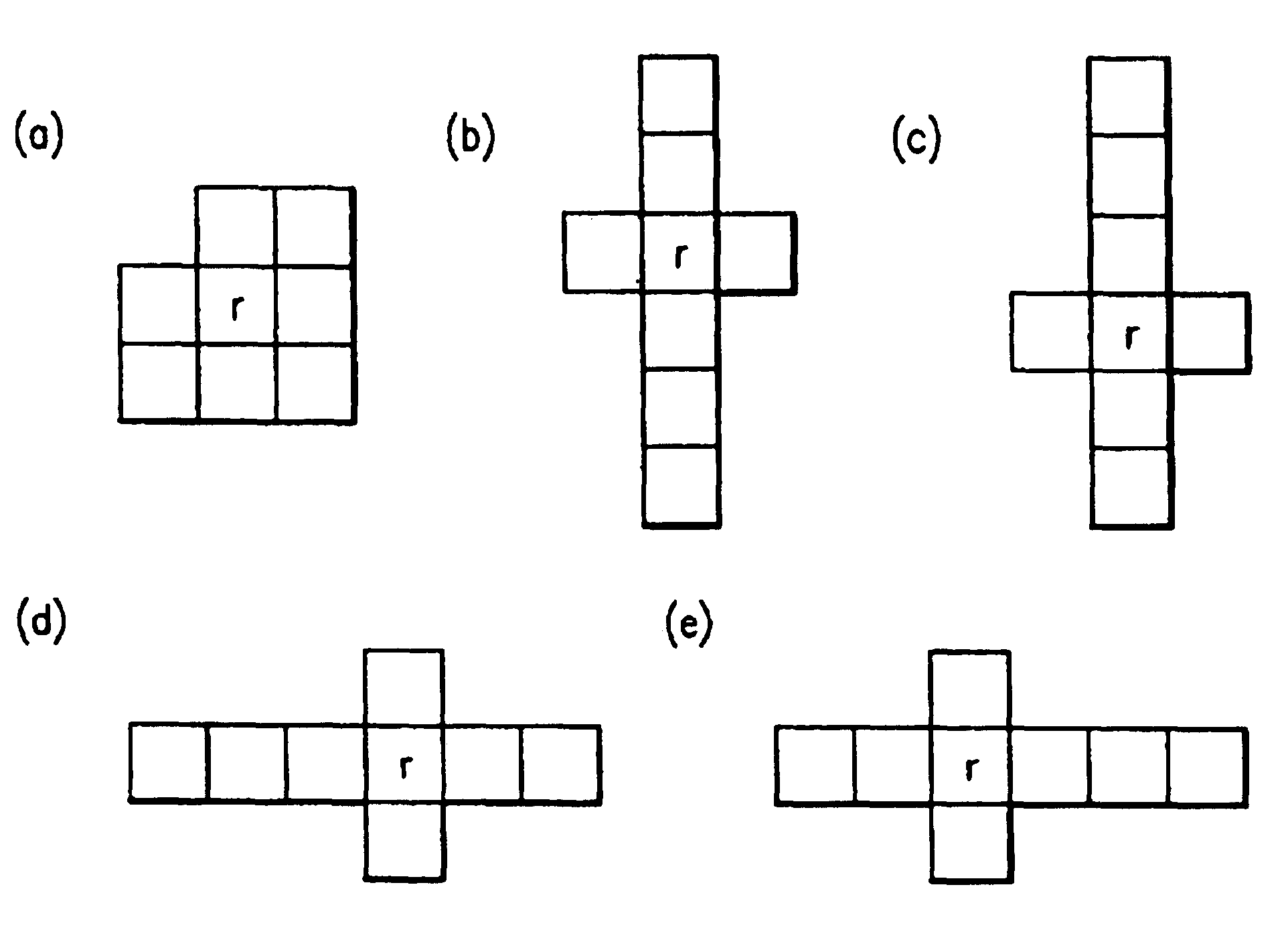
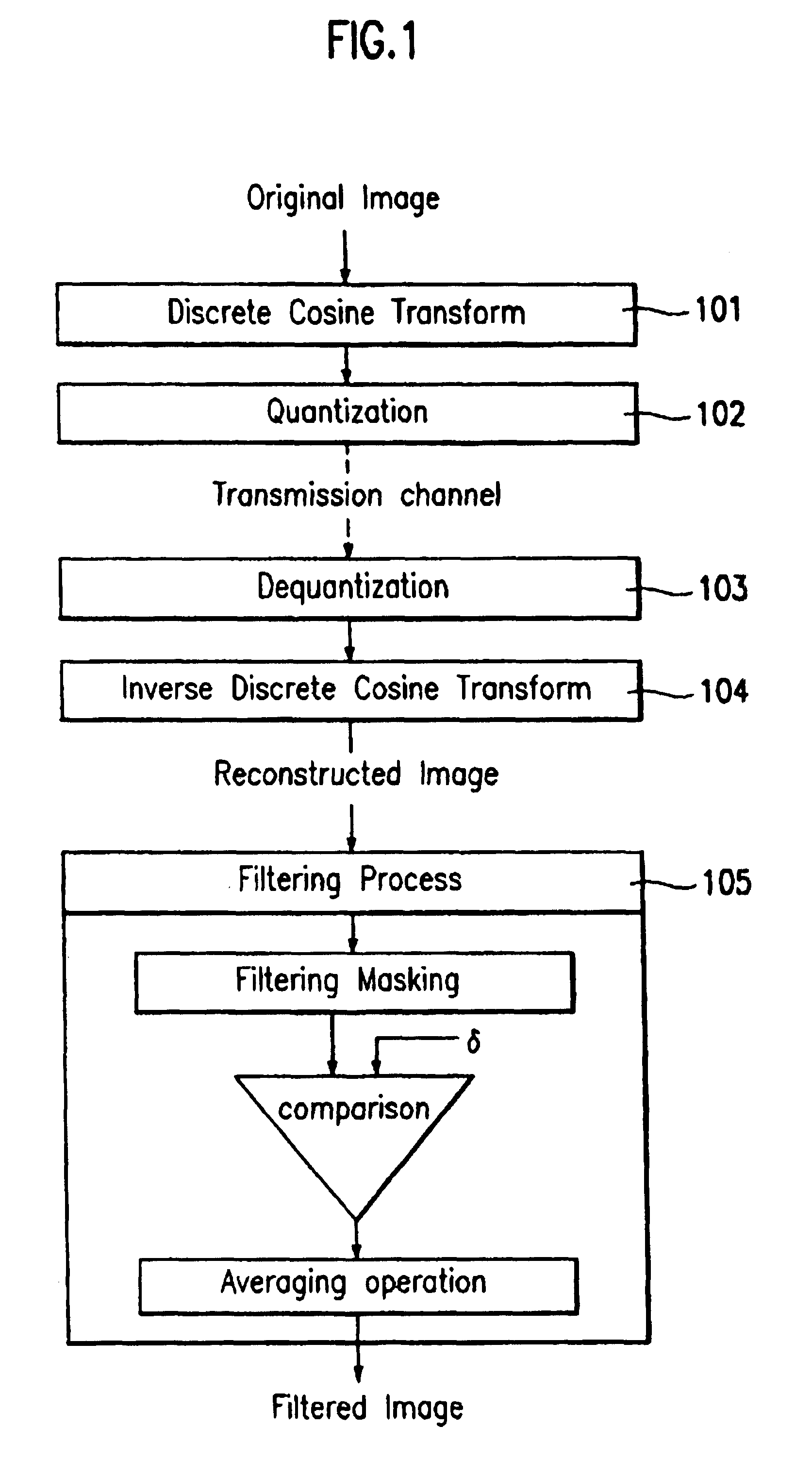
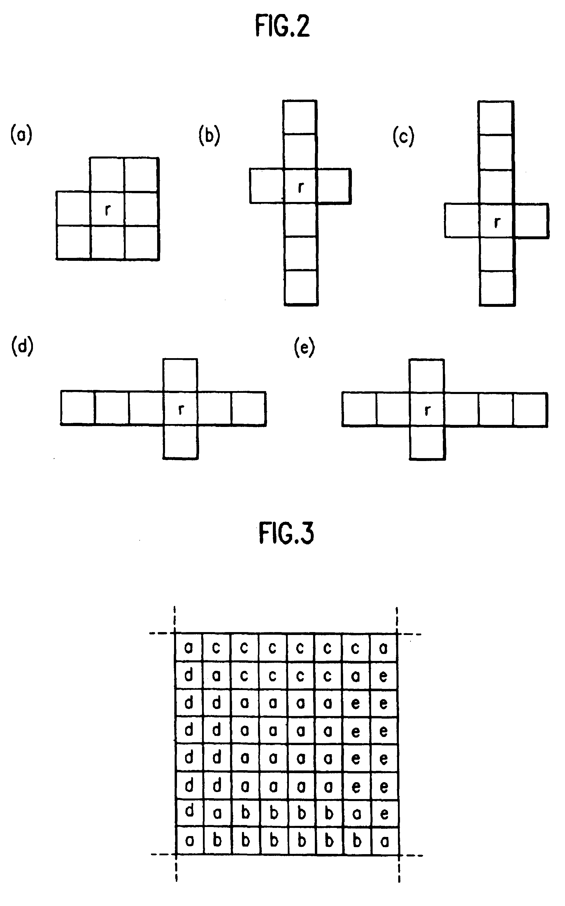
[0032]The present invention removes the block effect and ring effect appearing in a compression-coded image by an adaptive candidate pixel selection.

[0033]In the adaptive candidate pixel selection, a mask to be filtered is selected and pixels to be averaged are selected from the pixels in the selected mask. The pixels are selected by comparing differences between a pixel to be filtered and pixels surrounding the pixel to be filtered with a predetermined threshold value δ.

[0034]The threshold value δ is proportionate to a quantization step interval used for the quantization of DCT coefficients in a coder. Namely, the threshold value δ is varied according to the required objectives. For example, a threshold value δ used for the removal of the ring effect is smaller than the threshold value used for the removal of the block effect.

[0035]After the pixels to be averaged are selected, the averaging operation is performed with respect to the selected pixels and the pixel to be filtered. At...


PUM


Abstract

A method and apparatus to remove a block effect and a ring effect appearing in a compression-coded image is disclosed. The present invention is especially applicable to an image compression-coded at a low bit rate. In particular, the present invention includes a variety of masks for the removal of the block / ring effect. Thus, one mask is select for a pixel to be filtered. Moreover, candidate pixels to be averaged with the pixel to be filtered is selected from the pixels of the selected mask to better maintain the details of the image, and a weight is applied to improve the calculation speed of the averaging operation. More particularly, the masks according to the present invention have longer tabs toward adjacent blocks at boundaries of the given block to remove the block and ring effect.In the method, a pixel of an image is filtered according to a filtering methodology. The filtering methodology includes more than one comparison, and each comparison compares a respective determined value and a respective threshold. At least one of the respective thresholds may be based on quantization information of at least a portion of the image including the pixel. Each respective determined value may be based on a respective difference value, and each respective difference value may be based on a different difference. At least one the difference values may be based on the pixel being filtered and another pixel.

Description

DIVISIONAL REISSUE APPLICATIONS [0001]Notice: More than one reissue application has been filed for the reissue of Pat. No. 6,594,400. The four reissue applications are applications Nos. 11 / 102,889 (the subject application), 11 / 102,890, 11 / 102,888, and 11 / 102,891, all of which are divisional reissues of Pat. No. 6,594,400.FIELD OF THE INVENTION[0002]The present invention relates to a method of filtering an image decoder and more particularly, to a method of removing a block effect and ring effect which appear in a compression-coded image of an image decoder. The present invention is especially applicable to reduce the block and ring effects appearing in an image coded at a very low bit rate.DISCUSSION OF THE RELATED ART[0003]To encode either a still or motion image using a process based upon a discrete cosine transform (DCT), the image is divided into a plurality of segments. Typically, the image is divided into 8×8 segment blocks and the DCT operation is executed for each block. How...

Claims


Application Information

Patent Timeline
IPC IPC(8): H04N7/30G06T5/20G06T9/00H04N7/26H04N7/24
CPCG06T5/20G06T5/002H04N19/86H04N19/80G06T2207/10016G06T5/70
Inventor KIM, JAE MIN
Owner LG ELECTRONICS INC
Why Eureka
Try Eureka