Collision avoidance system for use in aircraft

a technology for aircraft and collision avoidance, which is applied in the direction of antennas, instruments, movable body antenna adaptation, etc., can solve the problems of commercial jet pilots being burdened, systems being complicated and expensive, and unavoidable collisions, etc., and achieves the effect of low cos

Inactive Publication Date: 2006-04-04
FLIGHT SAFETY TECH
View PDF19 Cites 29 Cited by
  • Summary
  • Abstract
  • Description
  • Claims
  • Application Information

AI Technical Summary

Benefits of technology

[0005]Accordingly, the primary object of this invention is to provide a low cost, reliable, universal, omni-directional, sensing system mountable on an aircraft for providing to the pilot of that aircraft an early warning of the presence of another nearby aircraft within the surrounding air space, thus enabling the pilot to take whatever maneuvering action is necessary to avoid a collision with the other nearby aircraft.
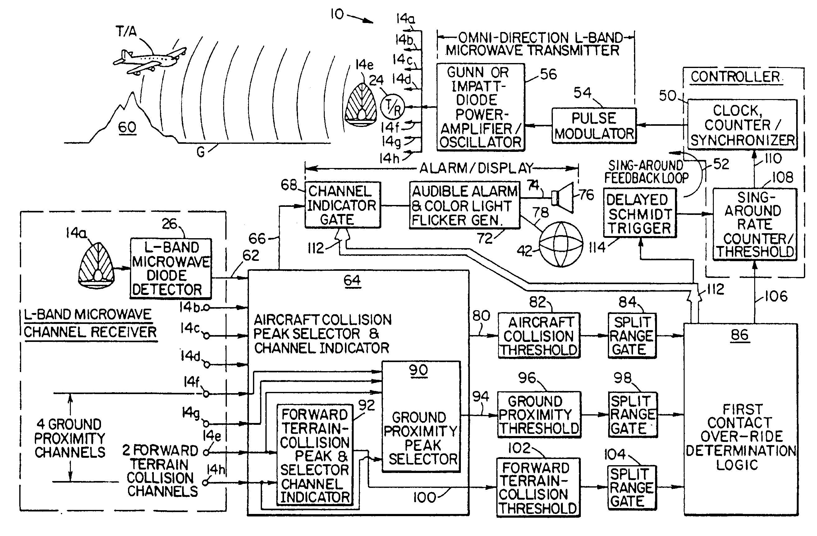
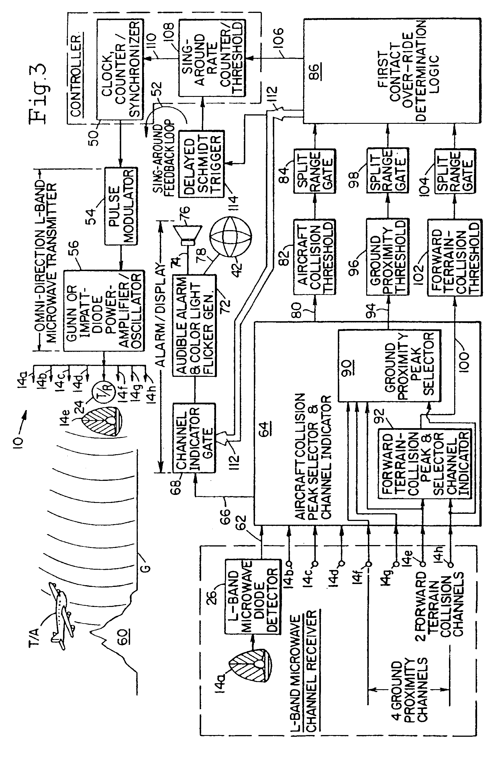
[0007]Still another object of the invention resides in the provision of the above described sensing system which includes an omni-directional L-band microwave antenna formed by a dielectric sphere cut into a plurality of “orange wedge” sectors, for example eight sectors, covering eight distinct transmitter / receiver direction patterns (up / down, port / starboard, forward / aft). An L-band microwave signal is transmitted simultaneously from all eight dielectric sections to provide an omnidirectional transmission covering a sphere of detection around the aircraft. In addition, the same eight dielectric sectors are employed together with suitable receiver circuitry for receiving microwave signals reflected back from other nearby aircraft. These sectors provide eight video channels by which a pilot of an aircraft receives information regarding the direction, closeness and rate of closure of the nearby aircraft so that a proper collision avoidance maneuver may be effected to avoid a disaster.

Problems solved by technology

With TCAS, the burden is on the commercial jet pilot to avoid a collision when an alert signal is received.
These systems however are very complicated and very costly and are used primarily on commercial sized aircraft.
Because of the high cost, these systems are rarely incorporated on smaller, privately owned aircraft whose pilots are often flying blindly under adverse weather and traffic conditions, a situation which often leads to an unavoidable collision.
General aviation pilots are also reluctant to incur the cost of installing a transponder without gaining autonomous control over averting a collision.

Method used


Image

  • Collision avoidance system for use in aircraft
  • Collision avoidance system for use in aircraft
  • Collision avoidance system for use in aircraft

Examples


Embodiment Construction

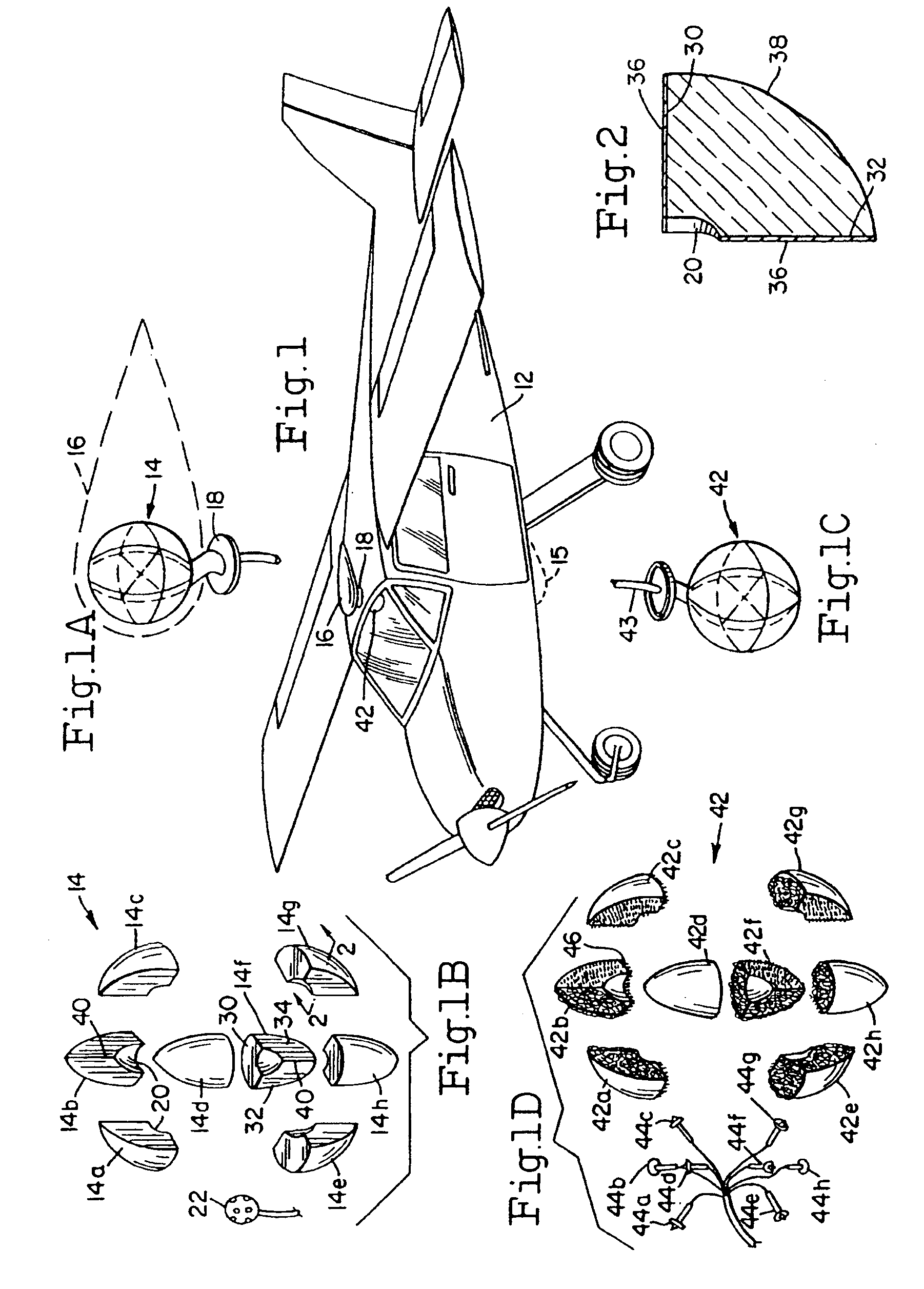
[0017]The novel UNICORN™ system 10 of the invention as used primarily with smaller private aircraft 12 includes a hollowed-out spherical antenna 14 (FIG. 1A) constructed from a dielectric material such as polystyrene or Lucite. Antenna 14 is about twelve (12) inches in diameter and is mounted within a protective streamlined, unicorn shaped, transparent radar dome 16 fixed at 18 on the brow of the aircraft above the plane's cockpit. Dome 16 is constructed of a material which does not interfere with operation of antenna 14.

[0018]As shown in the exploded view of FIG. 1B, antenna 14 is formed by dissecting a hollowed-out sphere into a plurality of equal “orange-wedge” sectors, e.g. eight equal octanes 14a, 14b, 14c, 14d, 14e, 14f, 14g and 14h. Each octant has an inner edge 20 scooped out so that when the octants are fastened together as in FIG. 1A, a central cavity is formed which houses a signal transmitting and receiving component assembly 22 within. As will be described in detail wit...


PUM


Abstract

A collision avoidance system mountable on an aircraft for providing to the pilot of that aircraft an early warning of the presence of another nearby threat aircraft within the surrounding air space. The system operates autonomously from that aircraft and does not require the presence of any matched system on board the threat aircraft. The system includes an omni-directional L-band microwave antenna formed by a dielectric sphere cut into eight equal “orange wedge” sectors covering eight distinct beam patterns. Eight L-band microwave signals are transmitted simultaneously from all eight dielectric sectors to provide a sphere of detection around the aircraft. The sectors also act as receivers for detecting a microwave signal reflected back from the threat aircraft, and indicating means provides information to the pilot regarding the direction, closeness and rate of closure of the threat aircraft.

Description

BACKGROUND OF THE INVENTION[0001]This invention relates generally to collision avoidance systems for aircraft and more particularly to a novel, low cost, universal collision, obviation and reduced near miss (UNICORN™) system which is particularly useful and affordable with small private aircraft.[0002]In conditions of crowded air traffic zones and / or low visibility it is necessary that the pilot of one aircraft be warned of the presence of a nearby aircraft so that he may maneuver his aircraft to avoid a disastrous collision. Systems known as TCAS (Traffic Alert and Collision Avoidance Systems) employ an interrogator mounted on a commercial jet aircraft and transponders carried on each aircraft it is likely to encounter. In this way, an interrogation is communicated by radar between the aircraft carrying TCAS and smaller, threat aircraft in the vicinity. This is done so that an enhanced radar signal is returned to the jet aircraft to enable the commercial pilot to avoid a collision....

Claims


Application Information

Patent Timeline
IPC IPC(8): G01S13/93G01S7/02G01S7/04G01S13/18G01S13/76G01S13/933G01S13/935
CPCG01S7/04G01S7/043G01S13/18G01S13/765G01S13/935G01S13/933
Inventor REES, FRANK L.
Owner FLIGHT SAFETY TECH
Why Eureka
Try Eureka