
Dental implants and methods for extending service life

a technology for dental implants and abutments, applied in the field of dental implants, can solve the problems of inability to attach a new crown or abutment, inability to prevent rotation, and relatively soft titanium metal

Inactive Publication Date: 2006-01-24
FRIED PAULA S +1
View PDF37 Cites 9 Cited by
  • Summary
  • Abstract
  • Description
  • Claims
  • Application Information

AI Technical Summary

Benefits of technology

[0016]Accordingly, it is an object of the invention to provide a method for rehabilitating the proximal end of an implant so as to prevent relative rotation of abutment or crown elements after the initial attachment means has failed.
[0018]Yet another object of the invention is to reduce the occasions when an implant that has osseointegrated with the jaw bone needs removal in its entirety.
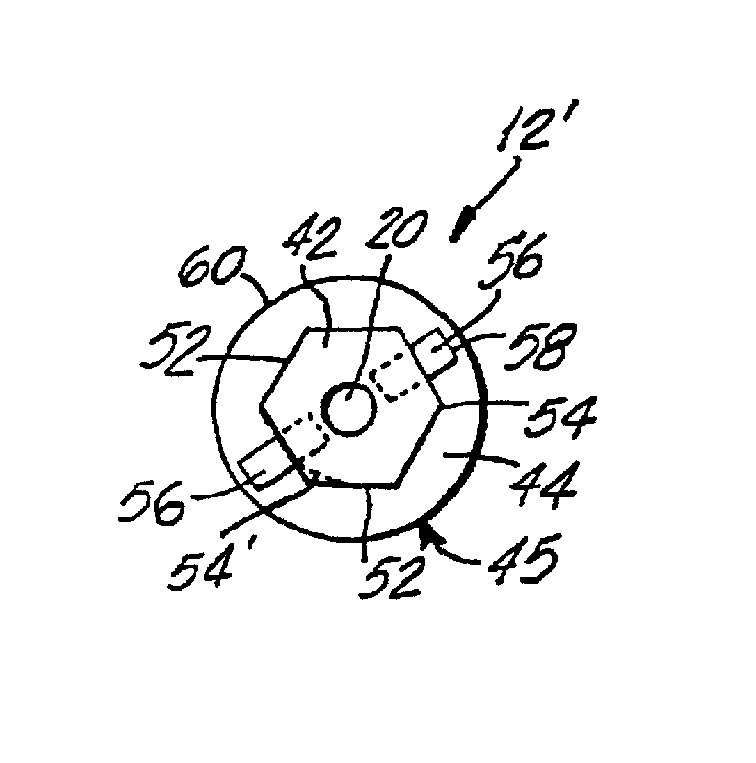
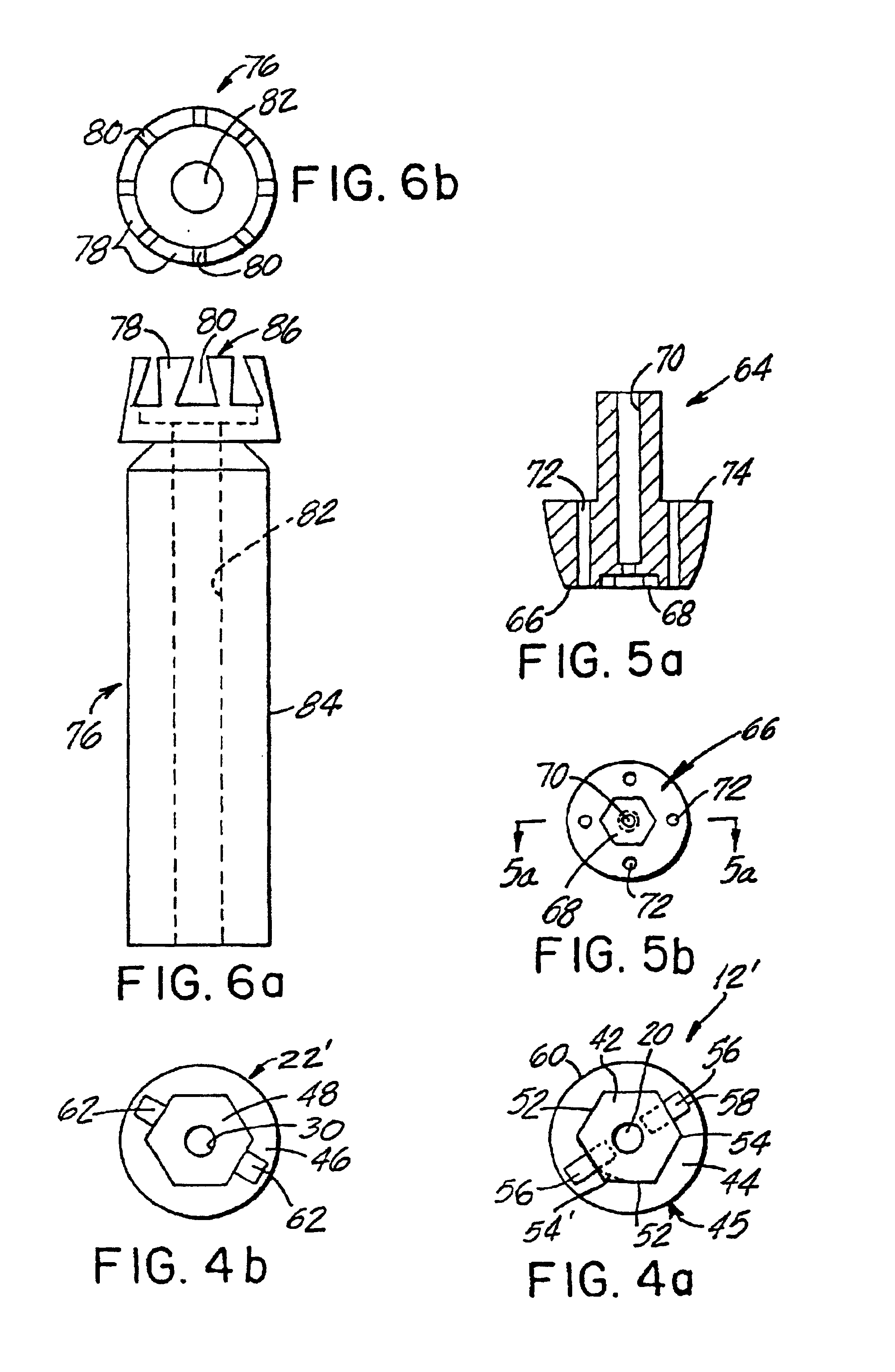
[0021]Further, an improved implant in accordance with the invention has a proximal protrusion that is generally square in cross section and further includes radial slots for use in threading the implant into the jaw bone. Thereby, no forces need be applied directly to the protrusion's external surfaces when inserting the implant for subsequent osseointegration. In this way, the surfaces of the protrusion that are used to maintain the abutment and / or crown against rotation relative to the implant are not subject to inadvertent damage during installation of the implant in the jaw bone. Further, the rotation resisting surfaces of the squared protrusion are broad and generally continuous and adjacent surfaces meet at 90° angles, or less. Forces tending to rotate the crown have little effect on the holding power of the proximal protrusion even should the edges of the protrusion be removed or become rounded.

Problems solved by technology

However, in a significant percentage of implants, a problem arises because titanium is a relatively soft metal.
An unacceptable degree of looseness often develops between the implant and the adjacent abutment or crown whereby there is relative rotation between the implant and the attached elements.
In time, the connection between the implant and the abutment and crown connected thereto does not prevent rotation and is unacceptable.
In these types of failure, for example, where the original protrusion on the implant was hexagonal in shape, it has been found that the corners of the hexagonal shape have been rounded to such a degree that it is not possible to attach a new crown or abutment and prevent rotation relative to the implant.
Also, the contours of the implant protrusion may become distorted, especially unfavorably rounded or stripped, during the process of threading the implant into the jaw bone.
Therefore, when hard bone is encountered, it is possible that an implant may be damaged beyond usefulness by an ill fitting socket type wrench that engages the outer surfaces of the protrusion and is used to drive-in the implant.
Unfortunately, after the implant has been joined to the jaw bone by osseointegration, and after years of this condition, it is extremely difficult, costly, and the cause of considerable suffering to the patient, to attempt to remove a damaged implant and replace it with another.

Method used


Image

  • Dental implants and methods for extending service life
  • Dental implants and methods for extending service life
  • Dental implants and methods for extending service life

Examples


Embodiment Construction

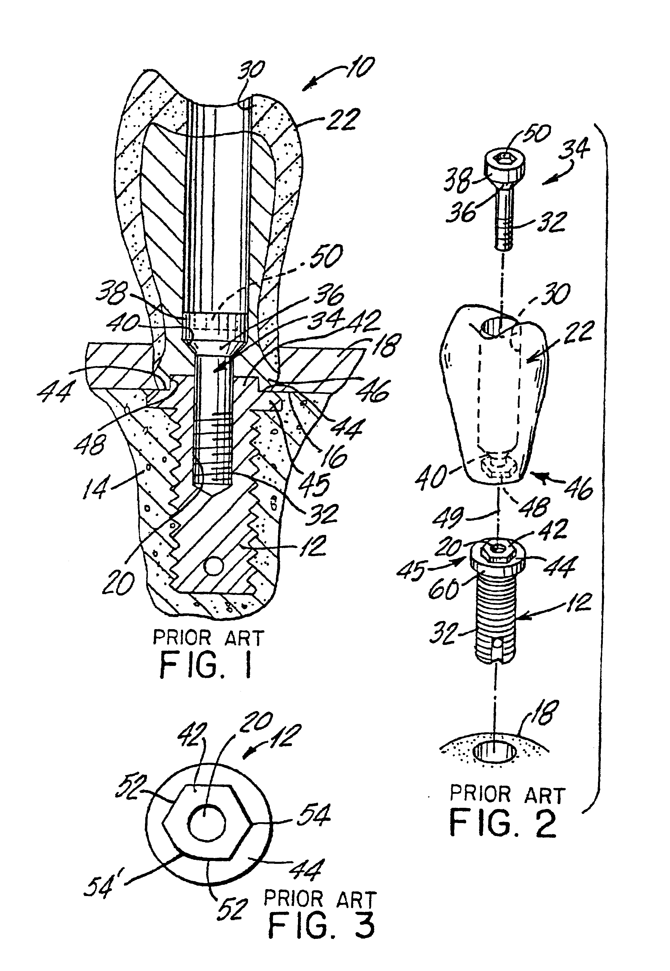
[0040]The present invention is concerned with the problem of rotation of a crown, or an abutment and crown, relative to a dental implant to which the abutment and crown are attached. In many applications, the abutment is omitted and a crown attaches directly to the implant. In every instance, the inherent problem of relative rotation is substantially similar. Accordingly, any description that includes an abutment, or any description that omits use of an abutment, is also applicable to the other construction.

[0041]In FIGS. 1-3, a dental prosthesis 10 of the prior art includes an implant 12 embedded in the spongiosa 14 of the jaw bone. After a healing period of several months, the implant 12 has become part of the bony structure by the known process of osseointegration. The implant 12 protrudes through the cortex 16 of the jaw bone, and the gum tissue 18 conceals the proximal end of the implant 12. A tapped hole 20 opens at the proximal end and is accessible between the parted gum tis...


PUM


Abstract

An implant has a proximal protrusion that is distinctly non-round even in a worn state, e.g. square in cross section, and may include radial slots for use in threading the implant into the jaw bone. No forces need be applied directly to the protrusion's external surfaces when inserting the slotted implant for subsequent osseointegration.

Description

[0001]This is a continuation in part of Ser. No. 08 / 380,850, filed Jan. 30, 1995, now U.S. Pat. No. 5,580,246.BACKGROUND OF THE INVENTION[0002]This invention relates generally to a dental prosthesis and more particularly to a dental prosthesis that is attached to an implant in the bone of a person's jaw.[0003]It is now common when it is desired or necessary to replace a missing tooth or teeth, that the gum is opened and an implant is imbedded in the bone structure beneath the gum. The implant is held initially by friction in a socket formed in the bone or the implant may be threaded into the bone. The gum is then closed over the implant and heals. When a proper material is used for the implant, the bone and implant grow together by a process known as osseointegration so that after several months the implant becomes a permanent part of the bone structure in the mouth. Titanium has been an effective implant material.[0004]Many firms manufacture complete systems of dental implants and ...

Claims


Application Information

Patent Timeline
IPC IPC(8): A61C8/00
CPCA61C8/0066
Inventor FRIED, PAULA S.COOPER, LEONARD
Owner FRIED PAULA S
Learn More