Smoke generating apparatus

a technology of generating apparatus and smoke, which is applied in the direction of lighting and heating apparatus, combustion air/fuel air treatment, machines/engines, etc., can solve the problems of heating element not working as intended, safety concerns, and heat build-up so as to increase the surface area of smoke generating fluid exposur

Inactive Publication Date: 2005-01-11
CPS PRODS
View PDF7 Cites 11 Cited by
  • Summary
  • Abstract
  • Description
  • Claims
  • Application Information

AI Technical Summary

Benefits of technology

What is required is a smoke generating apparatus that has improved combustion.
The smoke generating apparatus, as described above, with co-axial injection into a helical heating element provides more efficient combustion. Smoke generating fluid is injected onto the helical heating element, with the injection preferably angled upwardly toward an upper segment of the helical heating element. Any smoke generating fluid that is not immediately vaporized upon contact with the helical heating element falls by force of gravity onto a lower segment of the heating element. In addition, the helical heating element increases the surface area of heating element to which the smoke generating fluid is exposed. As will be hereinafter further described, it is preferred that the outer contact surface of the heating element be insulated, so that there is no direct contact between the smoke generating fluid and the current carrying core of the heating element.
Although beneficial results may be obtained through the use of the smoke generating apparatus, as described above, there remains a safety hazard should a short occur. Even more beneficial results may, therefore, be obtained when the helical heating element is insulated. When helical heating element is insulated it will not short out. When helical heating element is insulated a larger diameter wire may be used and the surface area exposure of the smoke generating fluid to heat is further increased.

Problems solved by technology

Although beneficial results may be obtained through the use of the smoke generating apparatus, as described above, having the smoke generating fluid in the same chamber as the helical heating element unavoidably results in a heat build up which raises the temperature of the smoke generating fluid over time.
This can cause operation problems by altering the viscosity of the smoke generating fluid.
This can also cause safety concerns as heat builds in the chamber.
The heating element will not work as intended if it is submerged.

Method used


Image

  • Smoke generating apparatus
  • Smoke generating apparatus
  • Smoke generating apparatus

Examples


Embodiment Construction

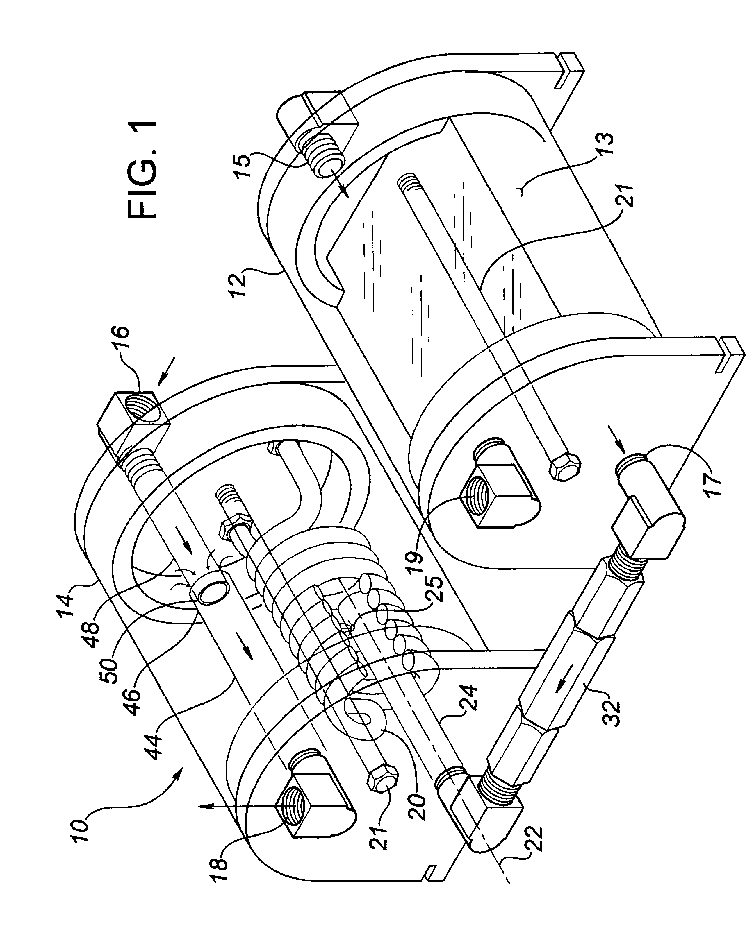
The preferred embodiment, a smoke generating apparatus generally identified by reference numeral 10, will now be described with reference to FIGS. 1 and 2.

Referring to FIG. 1, smoke generating apparatus 10 includes a reservoir 12 for smoke generating fluid 13 and a separate combustion chamber 14. Reservoir 12 has an air flow inlet 15 and a smoke generating fluid flow outlet 17. Reservoir 12 also has a port 19 to enable the addition of smoke generating fluid 13. Combustion chamber 14 has an air flow inlet 16 and an air flow outlet 18. The particular construction of reservoir 12 and combustion chamber 14 illustrated use clamping rods 21 to hold the components together. An insulated helical heating element 20 is disposed in combustion chamber 14. Helical heating element 20 has a central axis 22. A smoke generating fluid injection tube 24 is positioned along central axis 22 of helical heating element 20. Injection tube 24 has at least one upwardly angled injection port 25. Referring to ...


PUM


Abstract

A smoke generating apparatus includes a combustion chamber having an air flow inlet and an air flow outlet. A helical heating element is disposed in the combustion chamber. The helical heating element has a central flow axis. A smoke generating fluid injection tube is positioned along the central flow axis of the helical heating element.

Description

FIELD OF THE INVENTIONThe present invention relates to a smoke generating apparatus.BACKGROUND OF THE INVENTIONU.S. Pat. No. 5,107,698 which issued to Gilliam in 1992 discloses a smoke generating apparatus. Smoke generating apparatus, such as those disclosed by Gilliam, are used to test for hairline cracks and similar leaks that are not detectable by visual inspection. The location of the leak is detected by observing smoke exiting from the leak. The Gilliam apparatus has a container in which is disposed a heating element. The container is filled with a smoke producing liquid until the liquid level reaches, without submerging, the heating element. An air pump forces a flow of air to bubble up through the smoke producing liquid, propelling the smoke producing liquid into contact with the heating element. Any of the smoke producing liquid coming in contact with the heating element is vaporized. When the smoke producing liquid is vaporized, it becomes smoke. As the flow of air exits th...

Claims


Application Information

Patent Timeline
Patent Type & Authority Patents(United States)
IPC IPC(8): F02M15/04F02M15/00F22B29/06F22B29/00F41H9/06
CPCF41H9/06
Inventor LOBLICK, NORTON M.
Owner CPS PRODS
Why Eureka
Try Eureka