
Controlled-access broadcast signal receiving system

Inactive Publication Date: 2003-02-25
SONY CORP
View PDF33 Cites 39 Cited by
  • Summary
  • Abstract
  • Description
  • Claims
  • Application Information

AI Technical Summary

Benefits of technology

Yet another object of the present invention is to prevent the reproduction of transmitted data by a user without adequate payment for each reproduction.

Problems solved by technology

The drawback of such systems is that the user is often able to record the requested video programming for later reproduction.

Method used


Image

  • Controlled-access broadcast signal receiving system
  • Controlled-access broadcast signal receiving system
  • Controlled-access broadcast signal receiving system

Examples


first embodiment

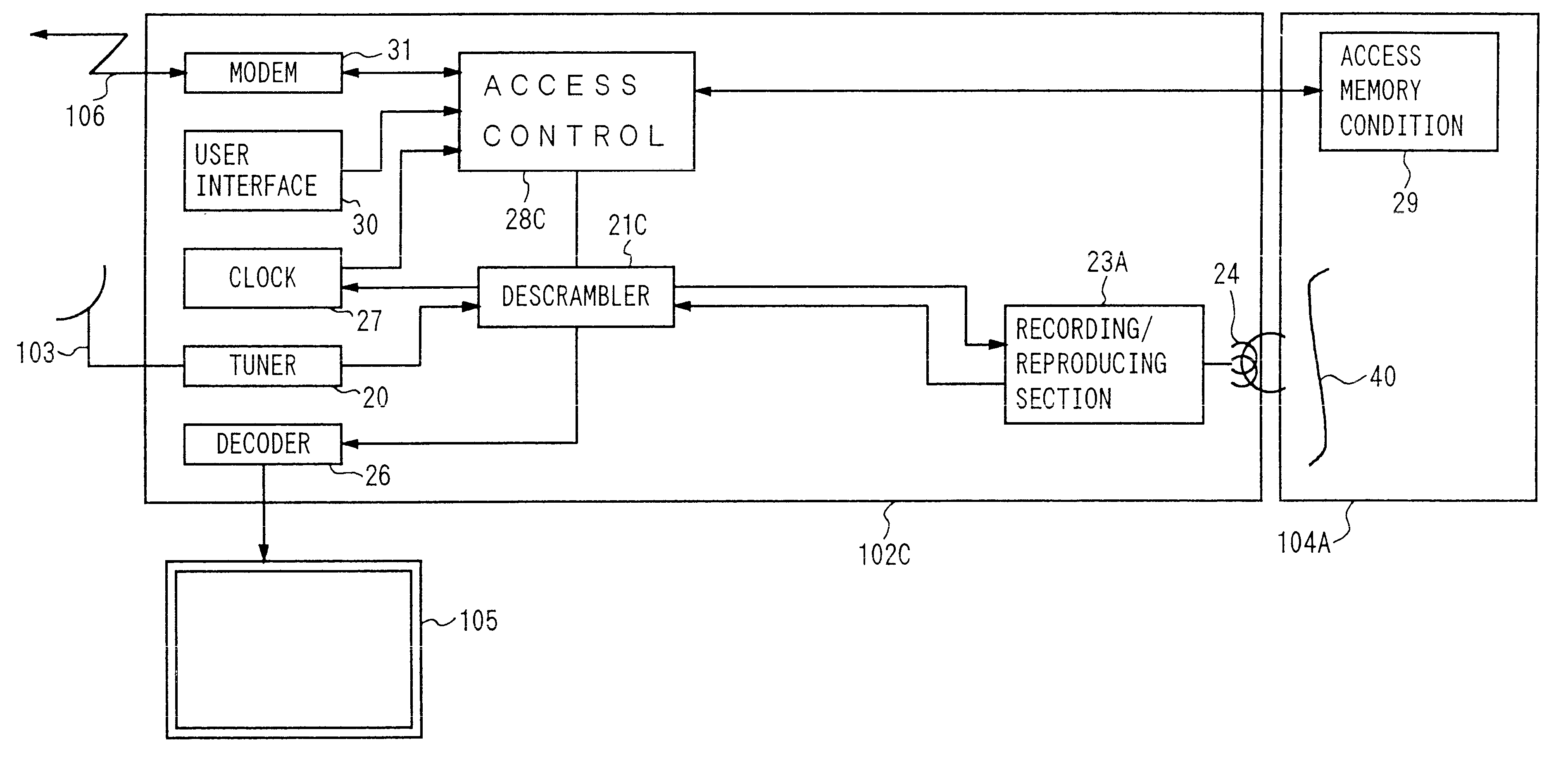
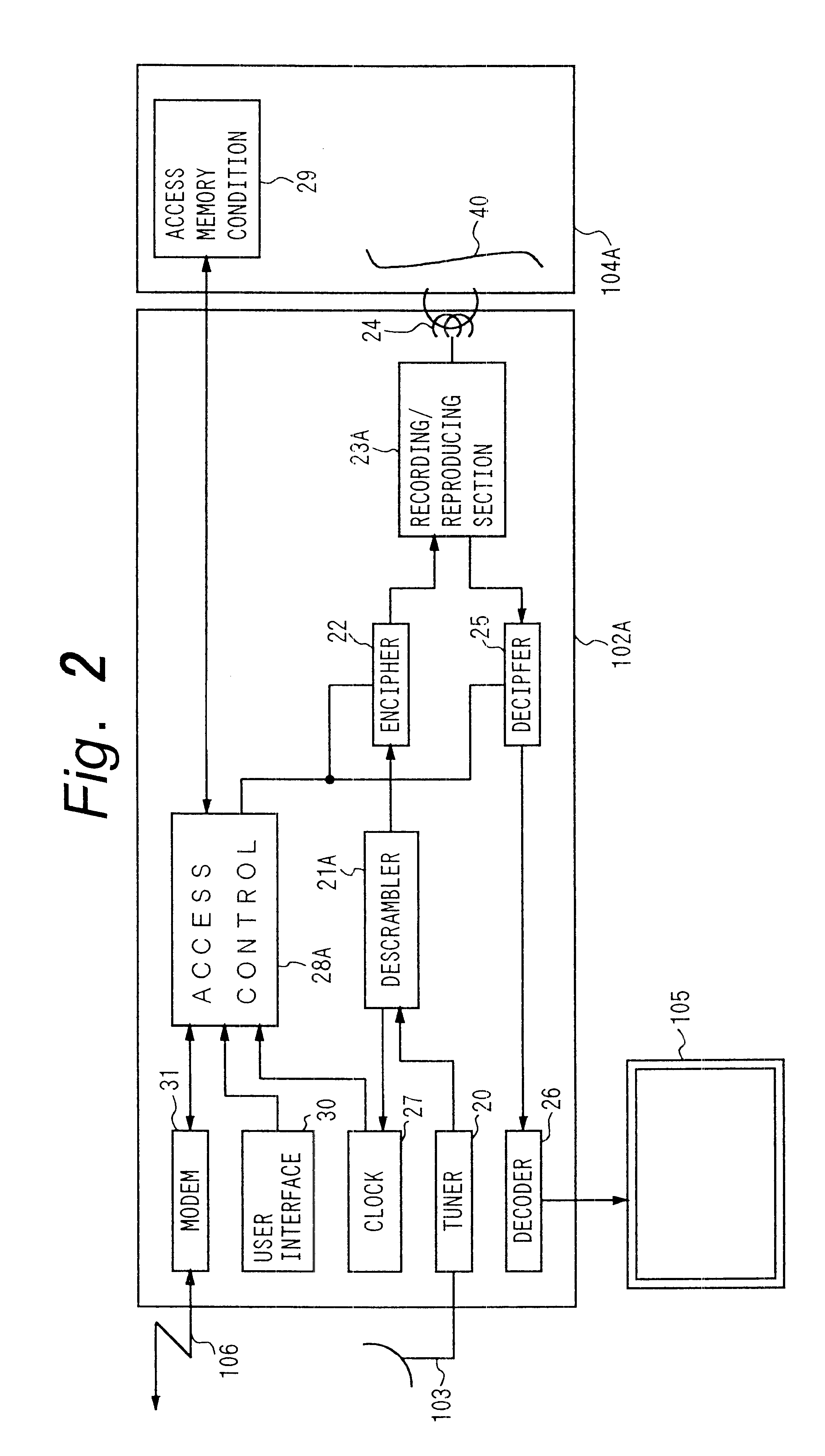
the controlled-access broadcast digital video signal receiving system 102 according to the present invention is illustrated in FIG. 2 as system 102A. Receiving system 102A, is adapted for receiving, descrambling, enciphering, recording, deciphering and decoding digital video signals; and is comprised of a tuner 20, a descrambler 21A, an encipherer 22, a recording / reproducing section 23A, a decipherer 25, a decoder 26, an access controller 28A, a user interface 30, and a modem 31.

Tuner 20 receives input digital video signals, selects particular digital video signals, and supplies the selected signals to descrambler 21A. Preferably, input digital video signals are satellite broadcast digital video signals acquired by satellite antenna 103 which is coupled to tuner 20. Alternatively, input digital video signals are acquired from another transmission medium that is coupled to tuner 20. Preferably, a user controls tuner 20 to select signals from among different input digital video signal...


PUM


Abstract

An apparatus and method for transferring from a broadcaster to a receiver a limited reproduction right in data. A signal indicating the limited reproduction right is transmitted by the broadcaster and stored by the receiver with the data. The receiver reproduces and processes the data as a function of this signal.

Description

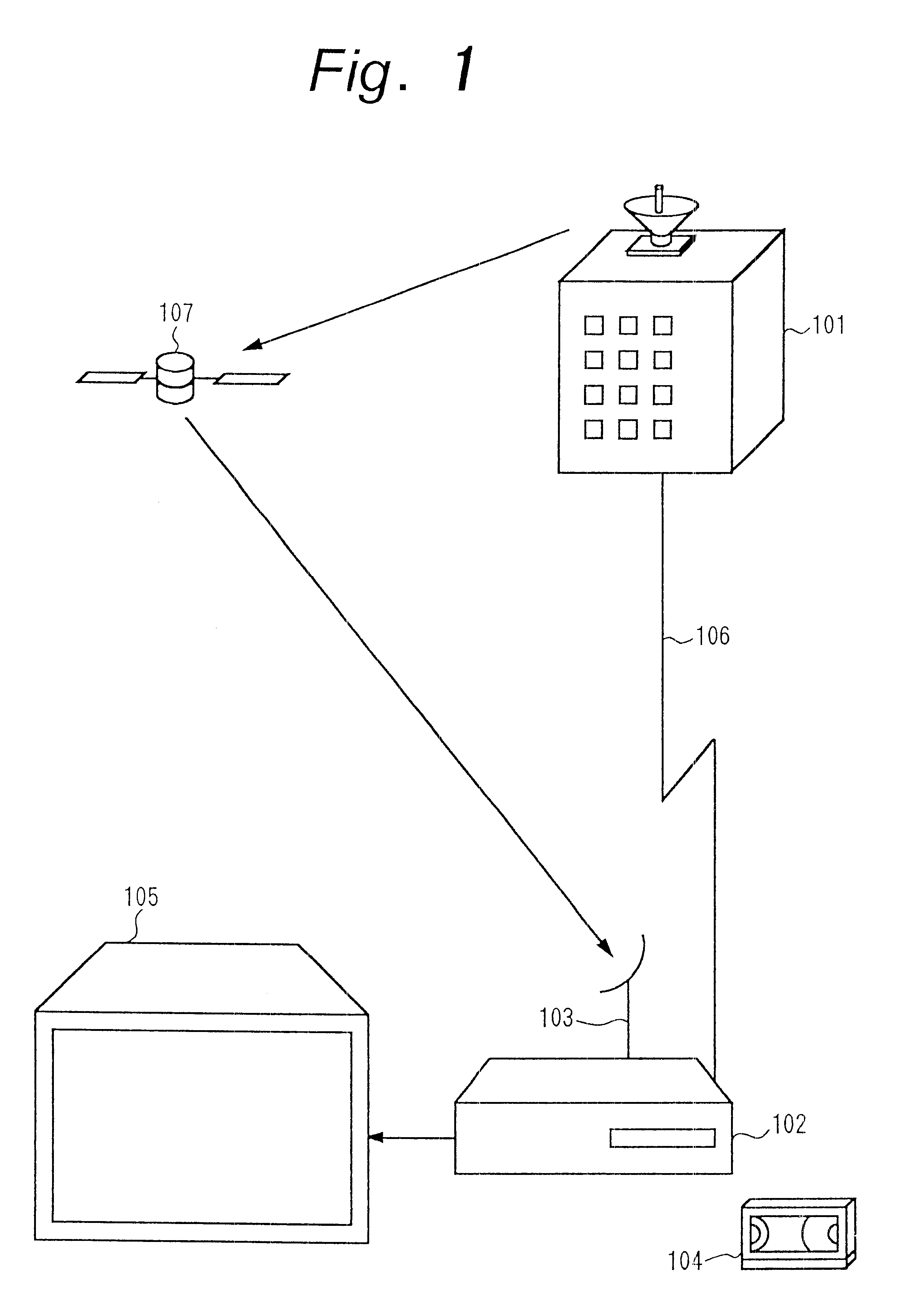
BACKGROUND OF THE INVENTIONThis invention relates to video data communication in which a limited reproduction right in video data is transferred between a broadcaster and a receiver.Commonly, video programming is transmitted from a broadcaster to a user via a satellite or cable communications system. In some systems, users are able to request, and broadcasters provide, select video programming through the use of individually addressable decoding receivers. The user's decoder is activated upon receipt of the user's address which is transmitted along with the requested video programming.The drawback of such systems is that the user is often able to record the requested video programming for later reproduction. This later reproduction occurs without any royalty payment to the broadcaster or other holder of copyrights in the video programming. Further, the recorded video programming can be disseminated by the user to others for additional reproductions without corresponding royalty paym...

Claims


Application Information

Patent Timeline
IPC IPC(8): H04N7/16H04N7/167H04N9/804H04N5/913G09C1/00G11B20/00H04L9/10H04N5/00H04N5/765H04N5/91
CPCG11B20/00086G11B20/00224G11B20/00246G11B20/00478G11B20/00746H04N5/76H04N5/913H04N7/163H04N7/1675H04N9/8042H04N21/2543H04N21/4334H04N21/4405H04N21/4408H04N21/47202H04N21/8355G11B20/0021H04N2005/91364H04N9/8205H04N2005/91321H04N2005/91328
Inventor TSUKAMOTO, JUNICHIGOTO, KOICHIFUKUSHIMA, SHINICHI
Owner SONY CORP
Learn More