
Lightweight handle

a light-weight, handle technology, applied in the direction of sealing, cell components, containers preventing decay, etc., can solve the problems of relatively high manufacturing cost and without drawbacks, and achieve the effect of eliminating any relative movemen

Inactive Publication Date: 2002-01-22
PELICAN PROD INC
View PDF25 Cites 46 Cited by
  • Summary
  • Abstract
  • Description
  • Claims
  • Application Information

AI Technical Summary

Benefits of technology

One object of the present invention is to provide a handle assembly which substantially eliminates any relative movement between the handle and the container during transportation.
A third object of the present invention is to provide a strong, light handle that will not corrode nor be weakened by chemical attack.
The above objects are realized by the present invention which is a light weight handle assembly adapted so that a user can stably lift and transport a heavy-duty container. In one embodiment, the handle assembly generally comprises a stationary bracket that mounts to a container wall and a movable handle which is pivotally connected to the bracket. In operation, when the stationary bracket is attached to the container wall, the movable handle may be pivoted between an inoperative position and an operative position. When the stationary bracket is removed or unattached from the container wall, the movable handle may be pivoted to a disengaged position where it may be easily assembled to or unassembled from the stationary bracket. This latter feature provides a handle assembly that is compatible with high production environments and which can be manufactured from a small amount of components.

Problems solved by technology

Handles of this type, although providing the required strength with less weight than prior conventional handles, are not without their drawbacks.
Although the performance of such handles is good and achieved at low weight, the cost of manufacture is relatively high.

Method used


Image

  • Lightweight handle
  • Lightweight handle
  • Lightweight handle

Examples


Embodiment Construction

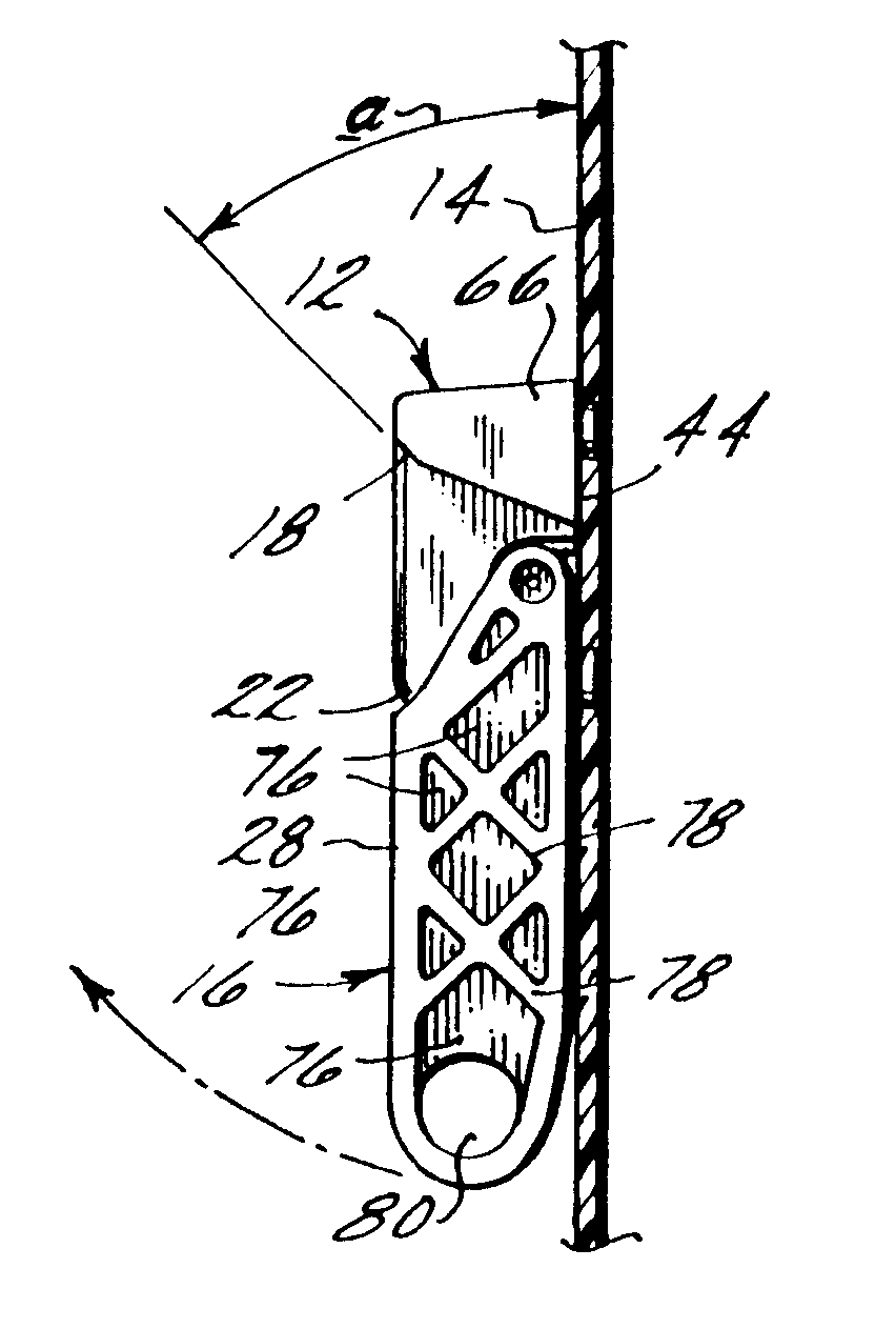
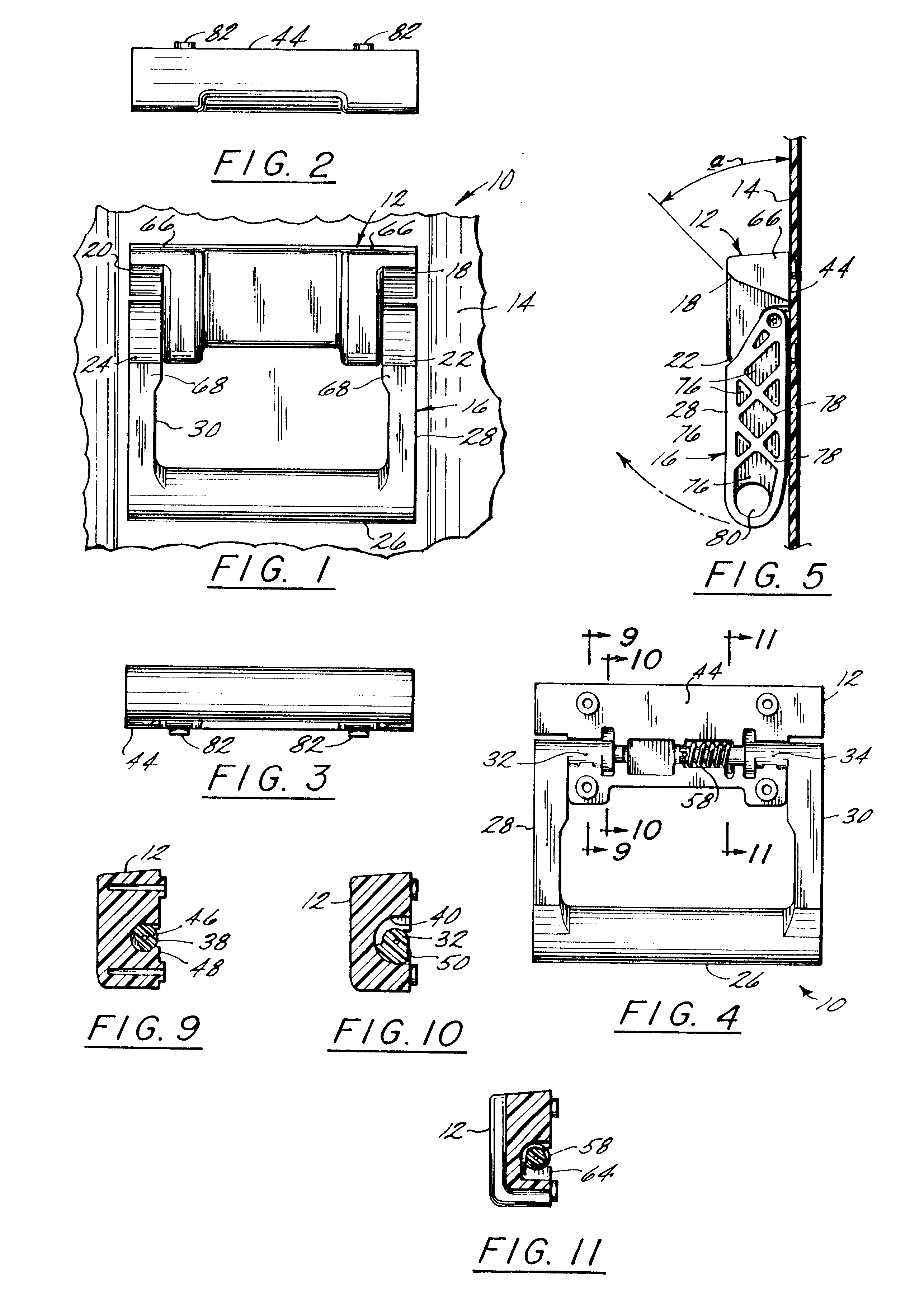
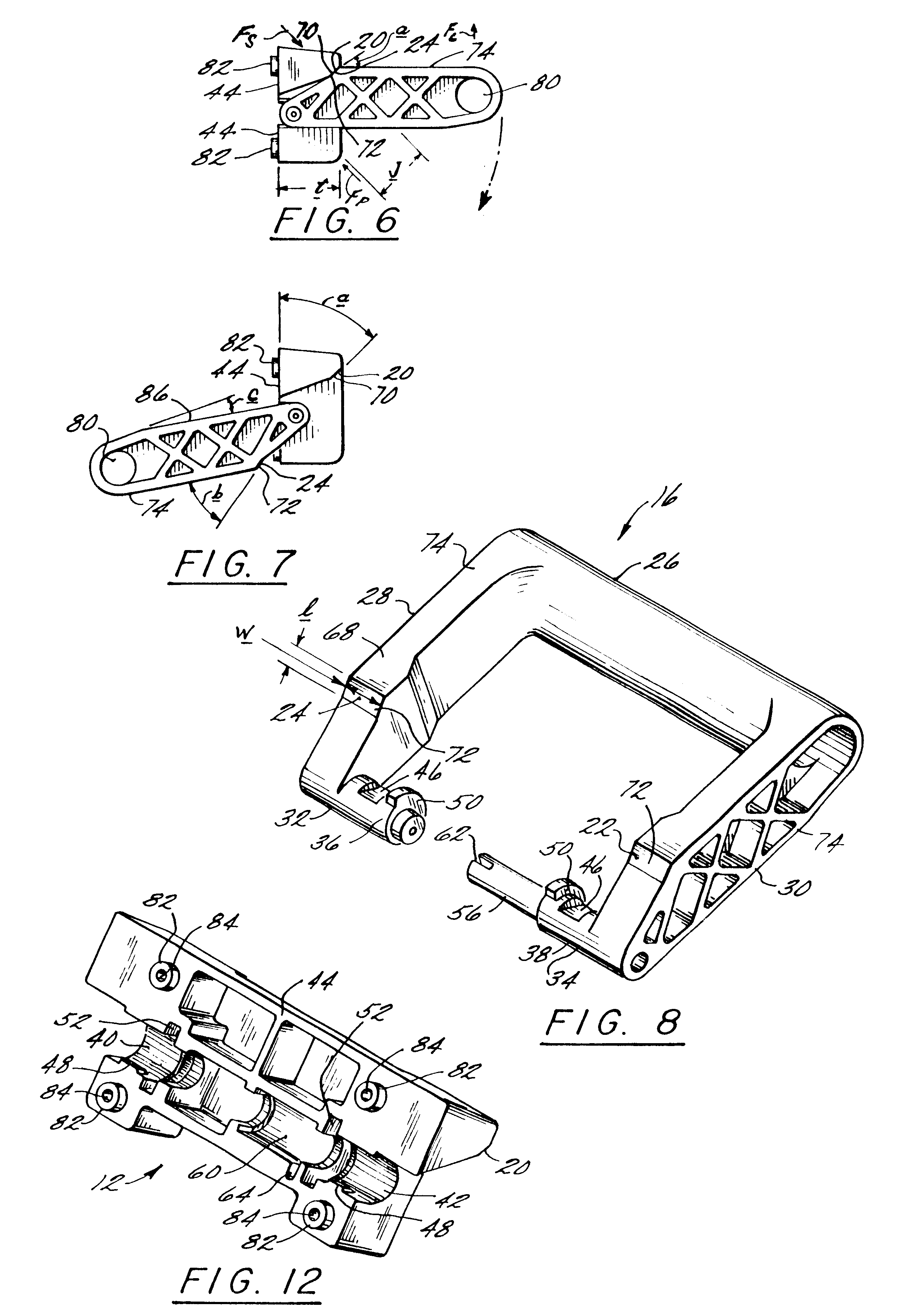
Referring to FIG. 1, the light weight handle assembly 10 according to the present invention is shown. The handle assembly 10 generally comprises a stationary bracket 12 mounted to a container wall 14 which may be a wall of a roto-molded container or any other container used to carry objects such as sensitive electronic equipment. The handle assembly 10 further comprises a movable handle 16 which is pivotally connected to the stationary bracket 12. When the stationary bracket 12 is connected to the container wall 14, the movable handle 16 may be pivoted between an inoperative position (FIG. 5) and an operative position (FIG. 6). When the stationary bracket 12 is not attached to or is removed from the container wall 14, the movable handle 16 may be pivoted to a disengaged position (FIG. 7) wherein the movable handle 16 may be easily assembled to or disassembled from the stationary bracket 12. This feature of the present invention allows the handle assembly 10 to be quickly assembled, ...


PUM


Abstract

Disclosed is a light weight handle assembly adapted to transport a heavy duty container which may contain sensitive electronic components. The handle assembly of the present invention generally comprises a stationary bracket which mounts to a container wall and a movable handle pivotally connected to the bracket. The bracket is formed with an inner portion that is adapted to rotatably engage with a pair of pivoting arms extending from the movable handle so that the light weight handle may easily be assembled and disassembled. The stationary bracket is also formed with two stationary stop members while each of the pivoting arms are formed with a corresponding movable stop member. The stationary stop members and movable stop members each have a substantially planar contact surface which are designed such that when the movable handle is pivoted to the lifting / operative position, the movable stop members are in contact with the stationary stop members with less stress in the materials than in conventional handles. The lower stresses enable a strong handle to be made of plastic material such as polyethylene.

Description

FIELD OF THE INVENTIONThe present invention relates generally to handles and more particularly to lightweight handles for lifting and transporting heavy-duty containers.BACKGROUND OF THE INVENTIONThe use of handles for lifting and transporting various objects is well known. For certain applications, it is desirable to use a handle that is light in weight, yet provides a stable and durable mechanism for lifting heavy objects. This is particularly true in the case of roto-molded plastic containers which are designed for the transport and handling of instruments and electronic equipment in hazardous environments such as those typically found in military, geophysical and news service applications.In the above application, the weight and size of loaded containers necessitate that two or more handles be distributed about the outside of the containers. Said handles are normally required to lie flat against the sides of the containers when not in use. When the container is being carried by ...

Claims


Application Information

Patent Timeline
IPC IPC(8): B65D25/28A45C13/26
CPCA45C13/26B65D25/2841Y10T16/513Y10T16/50B65D2525/288
Inventor HARDIGG, JAMES S.APONTE, RENE R.
Owner PELICAN PROD INC
Learn More