Eureka AIR delivers breakthrough ideas for toughest innovation challenges, trusted by R&D personnel around the world.

Tool holding mechanism for a motor driven surgical instrument

a technology of motor drive and tool holding, which is applied in the direction of manufacturing tools, wood boring tools, transportation and packaging, etc., can solve the problems of cumbersome and time-consuming replacement of tools

Inactive Publication Date: 2001-09-04
ANSPACH EFFORT
View PDF17 Cites 78 Cited by
  • Summary
  • Abstract
  • Description
  • Claims
  • Application Information

AI Technical Summary

Benefits of technology

A further object is to eliminate the use of separate collets for each tool bit of a different size.
Yet another object of the present invention is to provide a mechanism for attaching tools which prevents the motor spindle from rotating when the instrument is not in use. This feature inhibits the tool bit from accidentally rotating when the instrument is at rest.
The second tab engages the restrainer when the lock pawl is in the second position thereby preventing rotation of the body. This enables the tool bit to be replaced without the possibility of the motor accidentally rotating the body. In the first position of the lock pawl, the second tabs are disengaged from the restrainer thus allowing operation of the instrument.

Problems solved by technology

The need for corresponding sized collets and wenches not only made tool replacement time consuming and cumbersome, it required that additional items be stocked in the operating room.

Method used


Image

  • Tool holding mechanism for a motor driven surgical instrument
  • Tool holding mechanism for a motor driven surgical instrument
  • Tool holding mechanism for a motor driven surgical instrument

Examples


Embodiment Construction

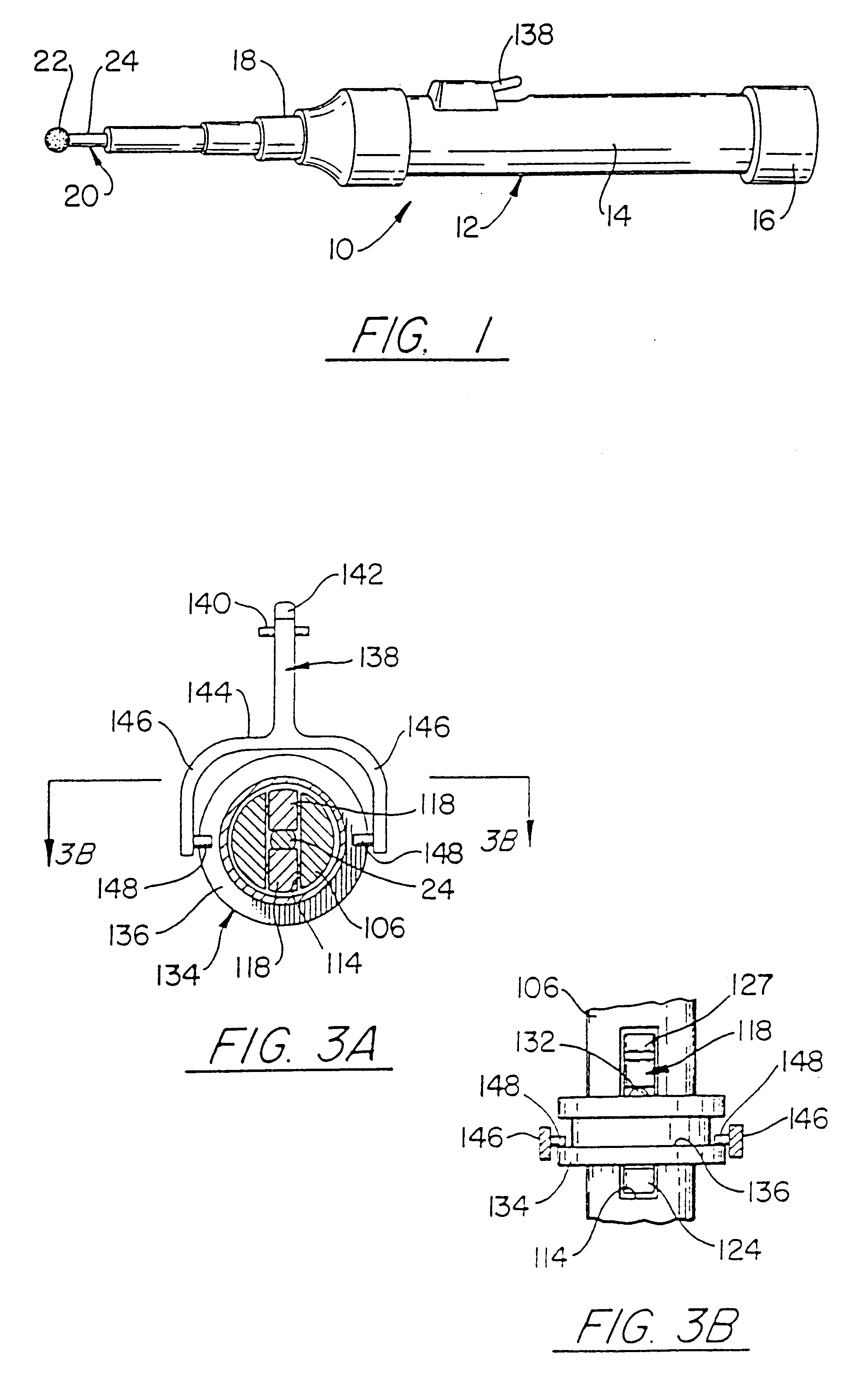
Referring initially to FIG. 1, a surgical instrument 10 that incorporates the present invention has a housing 12 which encloses a pneumatic motor 14. A hose (not shown) from a source of compressed air connects to a fitting 16 at one end of the housing 12. A removable nose 18 is attached to the other end of the housing and receives an interchangeable tool bit 20. The illustrated tool bit 20 has a spherical head 22 for shaping bone during the surgical procedure. Other tool bits have cylindrical, trapezoidal and other geometrical heads depending on their intended use. The head 22 is attached to a shaft 24 that extends through nose 24 and couples to a tool holder inside housing 12.

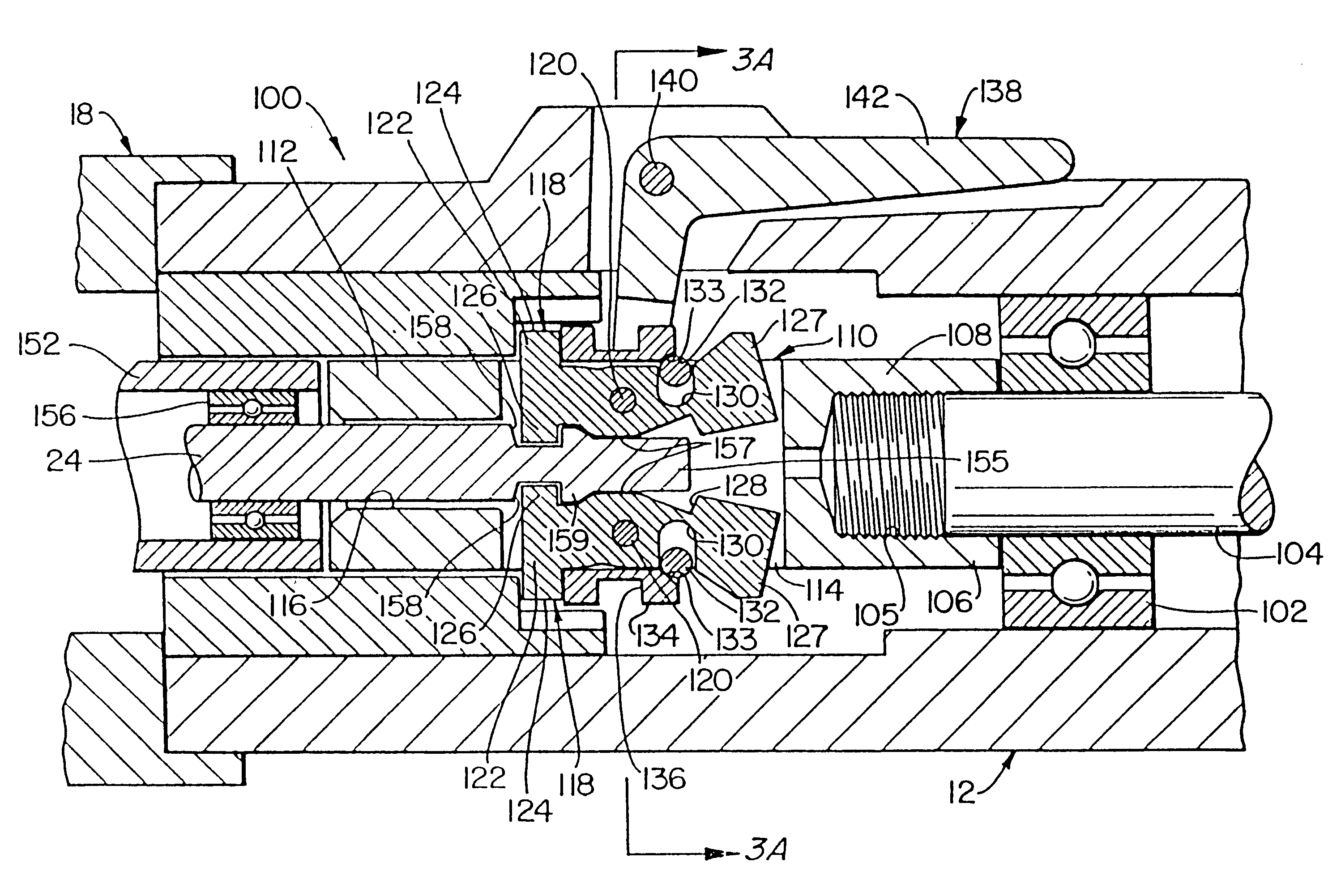
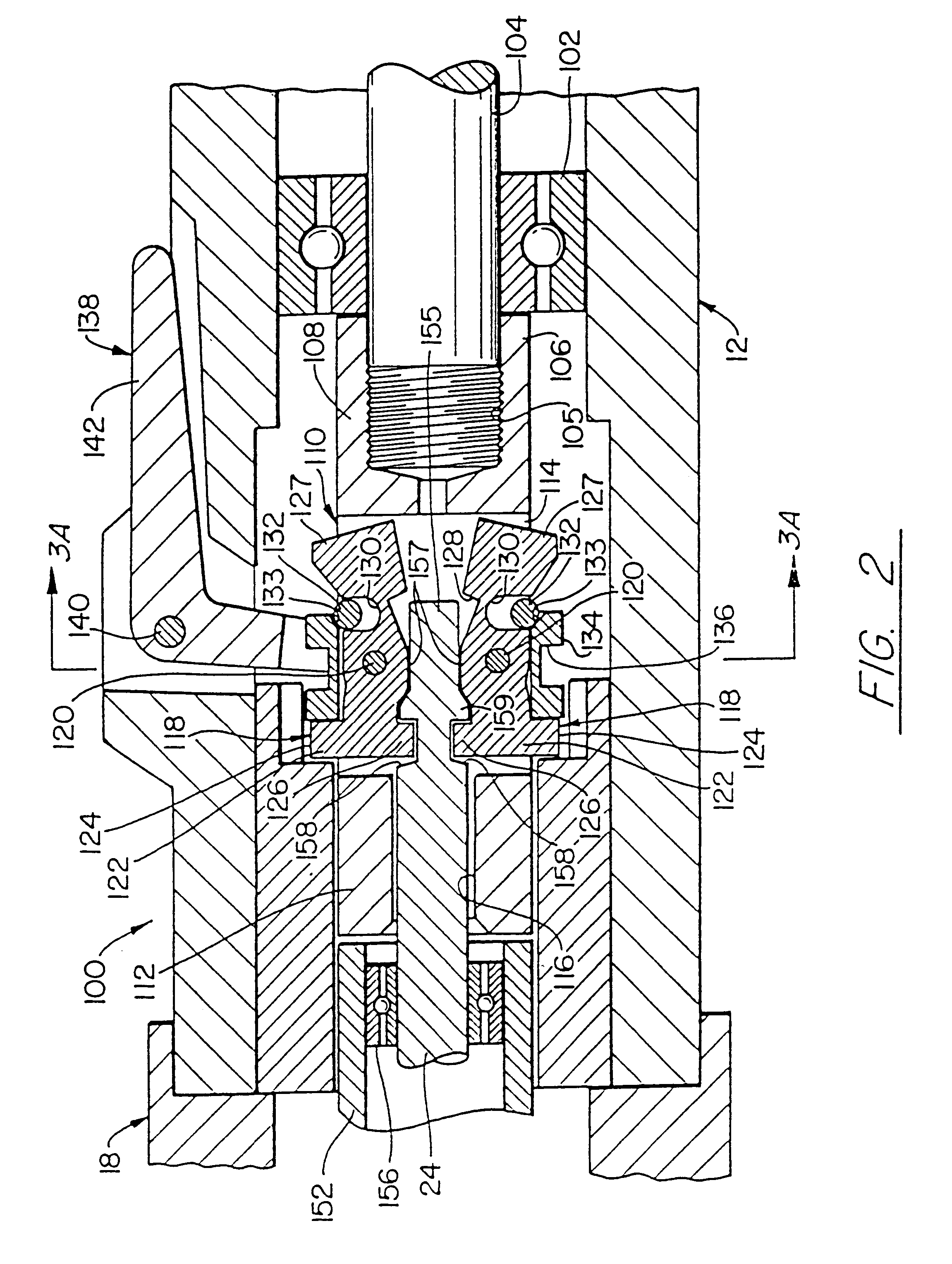
With reference to FIG. 2, the tool holder 100 within the motor housing 12 includes a main bearing 102 which receives the spindle 104 of the pneumatic motor 14 of the surgical instrument 10. The remote end of the motor spindle 104 has external screw threads which engage internal screw threads in an aperture 105...


PUM

PropertyMeasurementUnit
relative dimensionsaaaaaaaaaa
longitudinal lengthsaaaaaaaaaa
lengthsaaaaaaaaaa

Abstract

A surgical instrument has a housing which contains a motor that drives a spindle. A tool bit is attached to the motor by a holder that includes a body with a first end portion connected to the spindle, a central portion with a cavity therein, and a second end portion having an aperture through which a shaft of the tool bit passes into the cavity. A pair of lock pawls are pivotally mounted in the cavity with each one having a first tab that enters a slot in the shaft when the lock pawls are in a first position to hold the tool bit in the instrument. The first tabs retract from the slot when the lock pawls are in a second position for changing the tool bit. The lock pawls have second tabs that engage a restrainer only in the second position to prevent the body from rotating. A ring extends around the body and pivots the lock pawls between the first and second positions when the ring moved longitudinally along the body. A manually operable shift lever is pivotally coupled to the housing and move the ring longitudinally along the body.

Description

BACKGROUND OF THE INVENTIONThe present invention relates to motor driven surgical instruments; and specifically to mechanisms for releasably attaching a variety of different tool bits to the surgical instrument.Orthopedic and neurological surgeons frequently use a power driven surgical instrument to cut, shape and drill into bone. Such an instrument utilizes a small pneumatically driven motor contained in a cylindrical housing which is held by the surgeon during use. A hose from the source of compressed air attaches to one end of housing. A tool bit is received by a fitting at the other end of the housing and is rotated by the motor when compressed air is applied to the instrument.A wide variety of different shaped and sized tool bits are available for drilling into, cutting, and shaping bone as needed during a surgical procedure. Thus, the surgical instrument must be able to accept various kinds and sizes of tool bits.One common surgical instrument of this type used a collet to con...

Claims


Application Information

Patent Timeline
Patent Type & Authority Patents(United States)
IPC IPC(8): A61B17/16A61B17/00
CPCA61B17/162Y10T279/17769Y10T408/9098A61B2017/00477
Inventor DEL RIO, EDDY H.ANSPACH, JR., WILLIAM E.
Owner ANSPACH EFFORT
Why Eureka
Eureka Blog
Learn More