
Coffee and tea brewing apparatus and system

a coffee and tea brewing apparatus and technology of a system, applied in the field of brewing equipment and systems, can solve the problems of unsatisfactory coffee taste, unsatisfactory coffee taste, and long brewing time, and achieve the effect of superior coffee taste and constant brewing tim

Inactive Publication Date: 2001-05-15
JEFFERSON JR HARRY D
View PDF19 Cites 69 Cited by
  • Summary
  • Abstract
  • Description
  • Claims
  • Application Information

AI Technical Summary

Benefits of technology

The advantage of this new coffee maker is that it allows a user to brew coffee which will be of consistent quality regardless of the mount of coffee brewed. This is achieved by maintaining a constant "brew time," i.e. the time the ground coffee is exposed to hot water, regardless of the amount of coffee to be made. In the preferred embodiment, this is achieved by quickly dispensing heated water into a brewing chamber that contains the ground coffee. The flow of the water out of the brewing chamber is controlled so that the ground coffee is exposed to heated water in the brewing chamber for the desired brewing time.
The coffee making system of the present invention provides consistently superior tasting coffee and further allows the user to control the brewing time to adjust the coffee taste according to personal preference and experience and is adaptable to standard ground coffee and fine ground espresso type grind.

Problems solved by technology

Coffee beans contain approximately 600 chemical compounds, a high percentage of which result in bitter and poor tasting coffee, which is often incorrectly referred to as "strong coffee."
These undesirable compounds are normally released into brewed coffee when the hot water remains in contact with the ground coffee beans for relatively long durations.
Heated water (which in the prior art is usually only heated to between 170.degree. and 185.degree. F.) is pumped onto the coffee grounds in the plastic chamber at a relatively constant rate (which, as discussed below, is too low and thus results in a brew time that is too long).
The diverted water dilutes the brewed coffee and reduces its perceived "strength."
Although each of the above-described coffee brewing systems are somewhat satisfactory for brewing small quantifies of coffee, it has been found that the taste of coffee brewed using those systems is inconsistent over the range of volumes of coffee that those systems can produce.
Each of the prior art systems described above lacks a feature which will maintain a consistent brew time regardless of the quantity of coffee to be made in the system.

Method used


Image

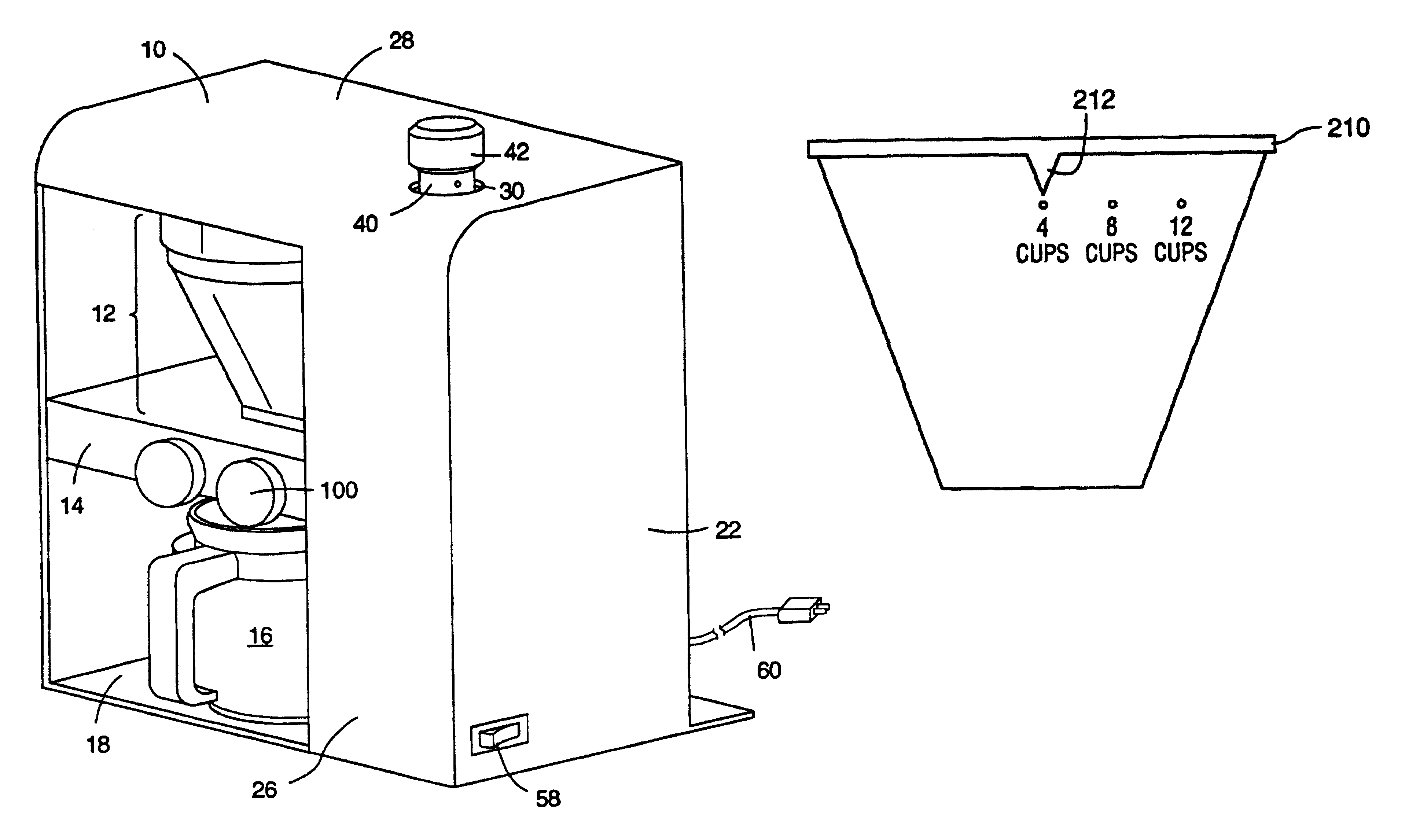
  • Coffee and tea brewing apparatus and system
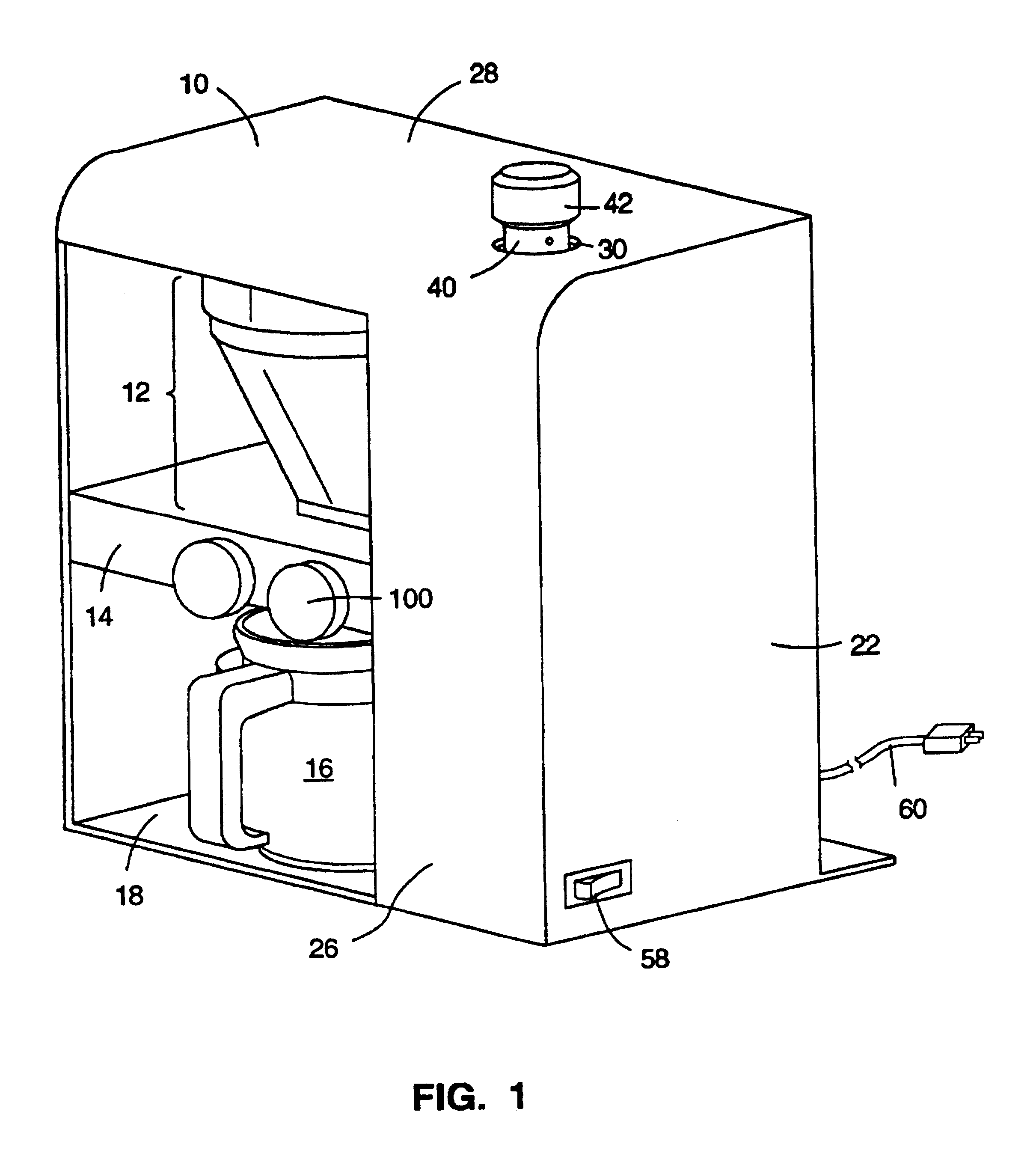
  • Coffee and tea brewing apparatus and system
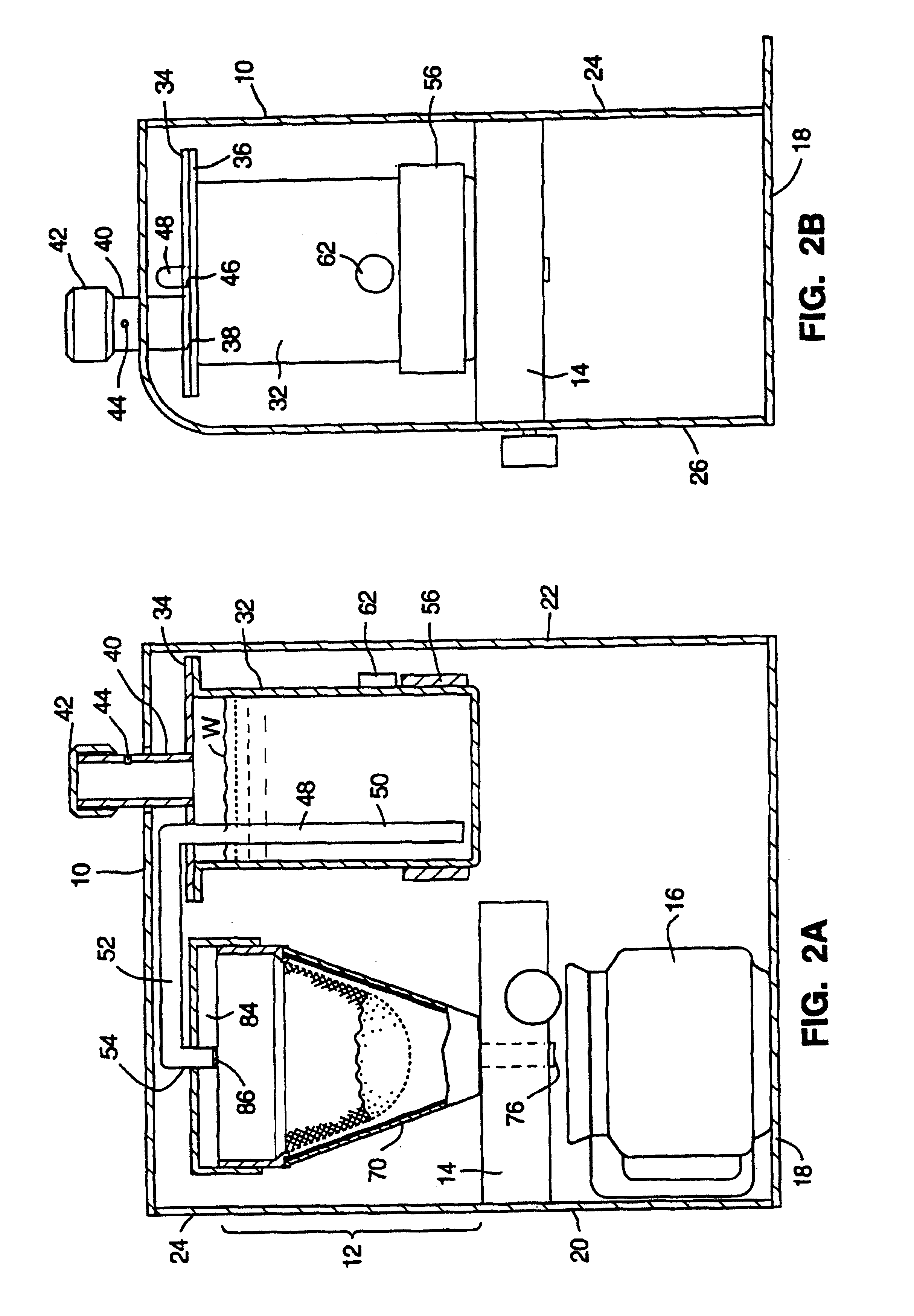
  • Coffee and tea brewing apparatus and system

Examples


third embodiment

a control valve assembly 98c is shown in FIGS. 10A and 10B. This control valve assembly 98c includes a rod 102c extending into a threaded bore 92c formed in the valve body 14c. At one end of the rod 102c is a control knob 100c which is located at the front 94c of the valve body 14c. The other end of the rod 102c is in contact with the silicone tube 76 extending from cone 70 (see FIG. 4C, or tubing 376 from cone 370, FIG. 6A), which extends through a substantially rectangular opening 88c in the valve body 14c. By rotating the control knob 100c in the manner described above, the rod 102c is made to constrict (FIG. 10A) or release (FIG. 10B) the silicone tubing 76.

fourth embodiment

a valve body 14d is shown in FIGS. 11A and 11B. As with the other valve body configurations, the valve body 14d includes an opening 88d through which the silicone tubing 76 from cone 70 (see FIG. 4C) at least partially extends. A stepper motor 130 is mounted to back wall 24d of the coffee maker housing 10 (housing shown in FIGS. 1-2B). A plunger 132 having a beveled end extends from the stepper motor 130 and through an opening in the back wall 24c. The plunger 132 and stepper motor 130 are coupled to one another such that activation of the stepper motor 130 moves the plunger 132 incrementally towards or away from the tube 76 in response to application of a drive signal to the stepper motor 130.

FIG. 12 is a simplified schematic diagram illustrating a coffee brewing system embodying the fourth embodiment of the valve body 14d. A user interface device 134 (which may be a keypad, dial, or any other form of input device) is provided which enables a user to input volume information repres...

sixth embodiment

a control valve is shown in FIG. 18. In this embodiment, which is particularly useful for brewing teas, the heated water is held in the brewing chamber for the duration of the desired brew time, and then quickly released into an underlying container at the end of the brew time.

Referring to FIG. 18, tube 76 which extends from cone 70 is equipped with a sensor 114 for detecting the presence of heated water in the brewing chamber 14. The sensor 114 can be one of several types of generally known sensors capable of sensing liquid, an increase in mass, or an increase in temperature. For example, the sensor 114 may be a thermocouple which detects an increase in temperature in the tube 76. Alternatively, the sensor 114 may be a conductivity probe which senses the presence of water inside the tube, since water is more highly conductive than air.

The opening of the tube 76 is covered by a valve door 116. Valve door 116 is pivotable about a pin 118 between an opened condition (shown in dashed l...


PUM


Abstract

A method and system for brewing a desired volume of coffee at a selected brew time, in which a volume of water corresponding to the desired volume of coffee is heated and directed into contact with coffee grounds in a brewing chamber. Contact between at least a portion of the heated water and the coffee grounds is maintained for approximately the selected brew time to form brewed coffee. The brewing time, however, is substantially independent of the desired volume of coffee to be brewed and is controlled by control of the rate at which heated liquid flows into or out of the brewing chamber. At the expiration of the brewing time, brewed coffee is released through an opening in the brewing chamber and into an underlying receptacle.

Description

FIELD OF THE INVENTIONThe present invention relates generally to the field of cooking appliances and particularly to the field of apparatuses and systems for brewing coffee and tea.BACKGROUND OF THE INVENTIONCoffee is brewed by placing hot water into contact with ground, roasted coffee for a given period of time. Coffee beans contain approximately 600 chemical compounds, a high percentage of which result in bitter and poor tasting coffee, which is often incorrectly referred to as "strong coffee." These undesirable compounds are normally released into brewed coffee when the hot water remains in contact with the ground coffee beans for relatively long durations. A primary influence on the taste of brewed coffee is therefore the "brew time," the amount of time that the heated water is in contact with the ground coffee beans. Brew time is similarly important to the brewing of teas.Experts in the coffee industry recommend brewing so-called "regular grind" coffee using brew times within t...

Claims


Application Information

Patent Timeline
IPC IPC(8): A47J31/06A47J31/00A23F5/24A47J31/02A23F5/26
CPCA23F5/26A23F5/262A47J31/002A47J31/0621
Inventor JEFFERSON, JR., HARRY D.PLOEGER, DALE W.
Owner JEFFERSON JR HARRY D
Learn More