
Lighting device

a technology of light source and light source, which is applied in the direction of illuminated signs, instruments, display means, etc., can solve the problems of reducing the attractiveness of the target object, affecting the overall effect, and affecting so as to optimize the overall effect and improve the effect of the light sour

Active Publication Date: 2018-06-05
SIGNIFY HLDG BV
View PDF21 Cites 3 Cited by
  • Summary
  • Abstract
  • Description
  • Claims
  • Application Information

AI Technical Summary

Benefits of technology

The invention relates to a lighting system that can change its light output to attract or hold a person's attention. The problem with existing light systems is that they often use a repeating light output that can quickly become annoying or discomforting. The inventors found that by using a dynamic light output that changes over time, people are more likely to keep their attention on the target object. This can be done by using a primary light output component that is the same for both the dynamic and static light modes, which ensures a smooth transition and prevents discomfort. The lighting device can also be used in conjunction with sensors to measure the person's distance from the target object and adjust the time dependency of the light effect accordingly. This system can be used as an interactive lighting device that increases attractiveness by changing its light output based on the person's presence and the distance between them and the target object.

Problems solved by technology

The inventors have found that monotonous repetition of a dynamic (e.g. pulsating) light effect at constant frequency very quickly results in discomfort, annoyance and reduced attractiveness of the target object.
Furthermore, the inventors have realized that with the known light systems the person whose attention has been attracted and who has been prompted to approach a target object, may rapidly loose his attention, or may even fail to recall to what object his attention was drawn in the first place.

Method used


Image

  • Lighting device
  • Lighting device
  • Lighting device

Examples


Embodiment Construction

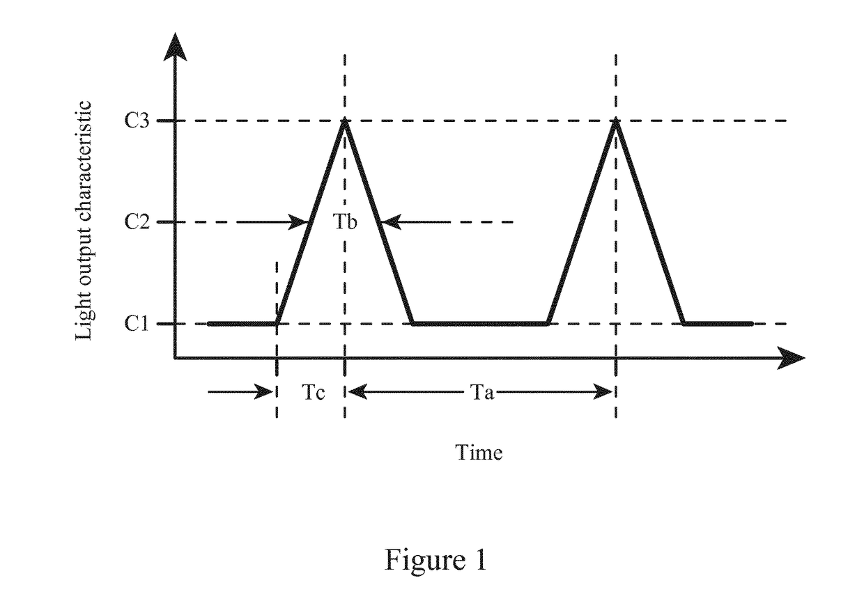
[0042]FIG. 1 illustrates several different examples of time constants that can each be used to characterize the waveforms of the first and second light output components. The examples shown are the time between subsequent pulses (Ta), the pulse width at half maximum (Tb), and the amount of change per time unit ([C3−C1] / Tc).

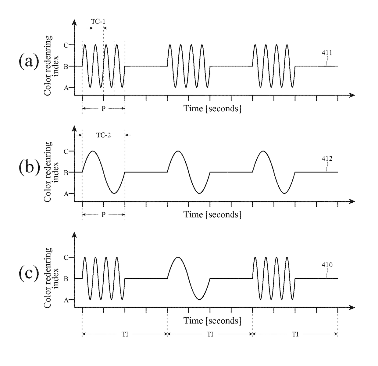
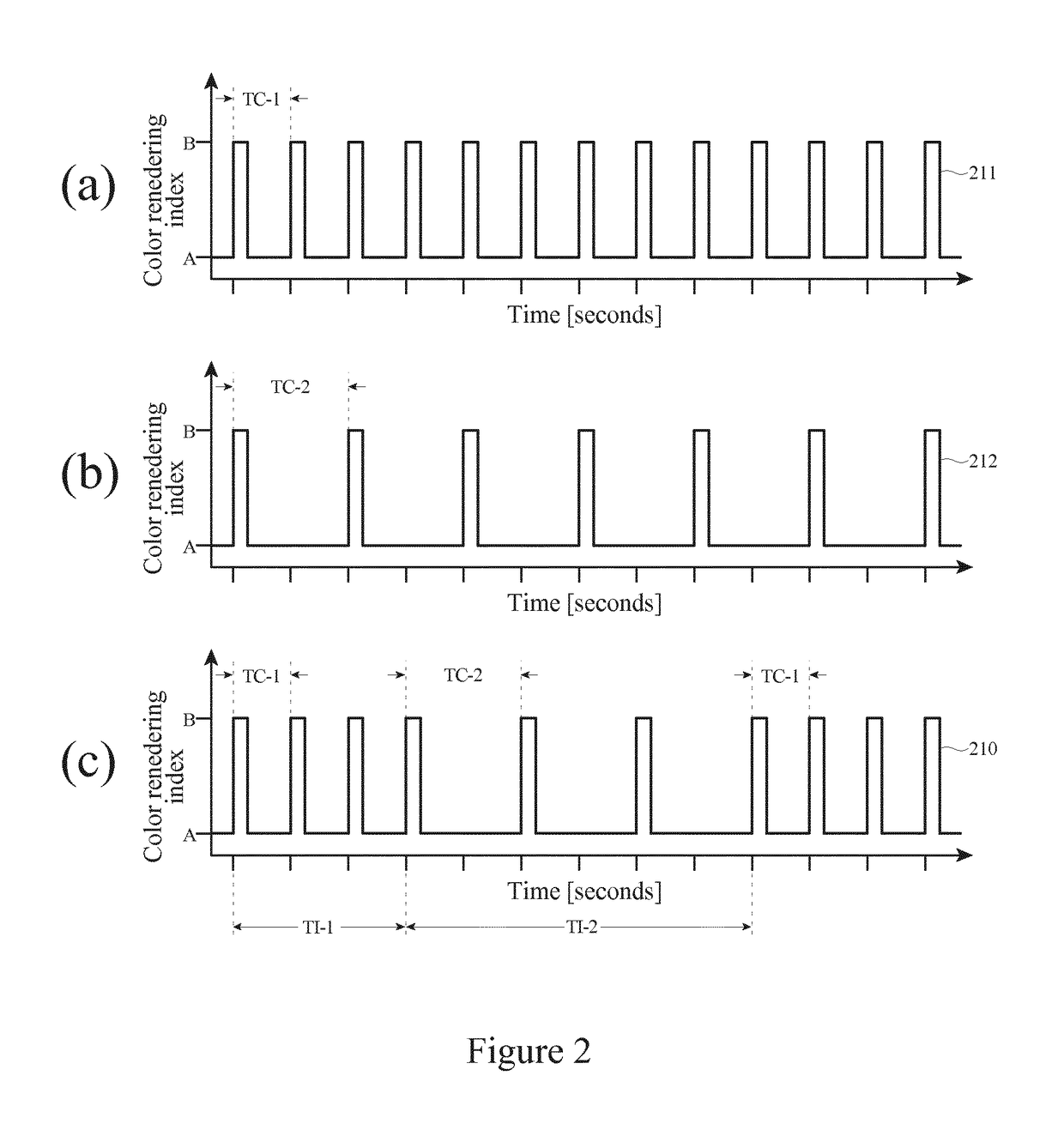
[0043]For an embodiment of the lighting device according to the present invention, FIG. 2 shows the time-dependent light output of the first light output component (see FIG. 2(a)), the second light output component (see FIG. 2(b)), and the primary light output (see FIG. 2(c)).

[0044]In this embodiment the primary light output characteristic is the color rendering index, which varies over time for the first light output component according to the first waveform 211, and for the second light output component according to the second waveform 212. The first waveform 211 and the second waveform 212 are both pulsed waves consisting of a sequence of pulses, wherein each p...


PUM


Abstract

The present invention relates to a lighting device for illuminating a target object with the objective to draw a person's attention to this target object. It alternatingly provides a relatively fast dynamic light output component and a relatively slow dynamic light output component, the former being predominantly for triggering a person's attention towards a target object, while the latter is mainly for enhancing the visual appearance of the target object, thereby keeping someone's attention for that object. For this purpose, the lighting device is arranged to provide a primary light output alternatingly comprising a first light output component and a second light output component. The lighting device comprises a switching controller for switching between the first light output component and the second light output component after a time interval. The primary light output has a perceived light intensity that remains constant over time within a margin of 10%. Each of the first and second light output components is characterized by a light output characteristic. The light output characteristic for the first light output component varies over time according to a first waveform, and the light output characteristic for the second light output component varies over time according to a second waveform. Each of the first and second waveforms is characterized by a time constant. The time constant has a first value for the first waveform and a second value for the second waveform, the first value being lower than the second value. The time interval for switching between the first and second light output components is between 0.1 seconds and 30 seconds.

Description

CROSS-REFERENCE TO PRIOR APPLICATIONS[0001]This application is the U.S. National Phase application under 35 U.S.C. § 371 of International Application No. PCT / EP2016 / 052993, filed on Feb. 12, 2016 which claims the benefit of EUROPEAN Patent Application No. 15155305.4, filed on Feb. 17, 2015. These applications are hereby incorporated by reference herein.FIELD OF THE INVENTION[0002]The invention relates to a lighting device for illuminating a target object with the objective to draw attention to this target object.BACKGROUND OF THE INVENTION[0003]In many everyday situations, drawing a person's attention to an object is desirable, or it may even be essential. For example, a retailer wants to draw the attention of possible customers to the goods that he is selling. Furthermore, when people are participating in traffic their attention should be drawn to traffic signs.[0004]Lighting can be used to draw attention, for example in the form of blinking and / or color changing illumination, whic...

Claims


Application Information

Patent Timeline
Patent Type & Authority Patents(United States)
IPC IPC(8): H05B37/02H05B33/08G09F13/02H05B44/00
CPCH05B37/0281H05B33/0872G09F13/02H05B33/0857H05B37/0227Y02B20/42H05B45/20H05B47/16H05B47/105H05B45/327Y02B20/40H05B47/115
Inventor KURT, RALPHWAGEMANS, WIEBESEKULOVSKI, DRAGAN
Owner SIGNIFY HLDG BV
Learn More