
Multi-LED components

a technology of inorganic light-emitting diodes and components, applied in the direction of printed circuit parts, printed circuit repair/correction, programmable/customizable/modifiable circuits, etc., can solve the problems of large system with many components, defective elements of many components, undesirable brightness or power usage,

Active Publication Date: 2018-05-22
X DISPLAY CO TECH LTD
View PDF330 Cites 29 Cited by
  • Summary
  • Abstract
  • Description
  • Claims
  • Application Information

AI Technical Summary

Benefits of technology

This patent describes a way to control the color and brightness of LED lights in a variety of applications such as displays and lamps. By using different combinations of LEDs, the system can create the impression of white light. The patent also addresses issues that arise when LEDs don't emit light or conduct too much current. The technical effect of this patent is to provide a simple solution for controlling LED circuits and avoiding common problems in light-emitting devices.

Problems solved by technology

Because no manufacturing process is perfect, any large system with many components can have defective elements.
In particular, inorganic light-emitting diodes are subject to manufacturing defects that increase the amount of current passing through the LED when provided with power, resulting in an undesirable brightness or power usage, or system control problems, for example.
An undesired increase in current can also overheat the LEDs.
However, these approaches either require complex or expensive circuit components in association with each LED or result in diminished light output.
However, the use of redundant emitters can be expensive and generally does not address problems with LEDs that conduct too much current.

Method used


Image

  • Multi-LED components
  • Multi-LED components
  • Multi-LED components

Examples


Embodiment Construction

[0039]The present invention provides, inter alia, a simple way to provide robust LED emission systems, to overcome LED manufacturing faults in a multi-LED component, and to enable simple detection or repair of the multi-LED component. The multi-LED component in accordance with certain embodiments of the present invention can be used in a wide variety of applications, including, for example, in displays, for illumination, and for indicators.

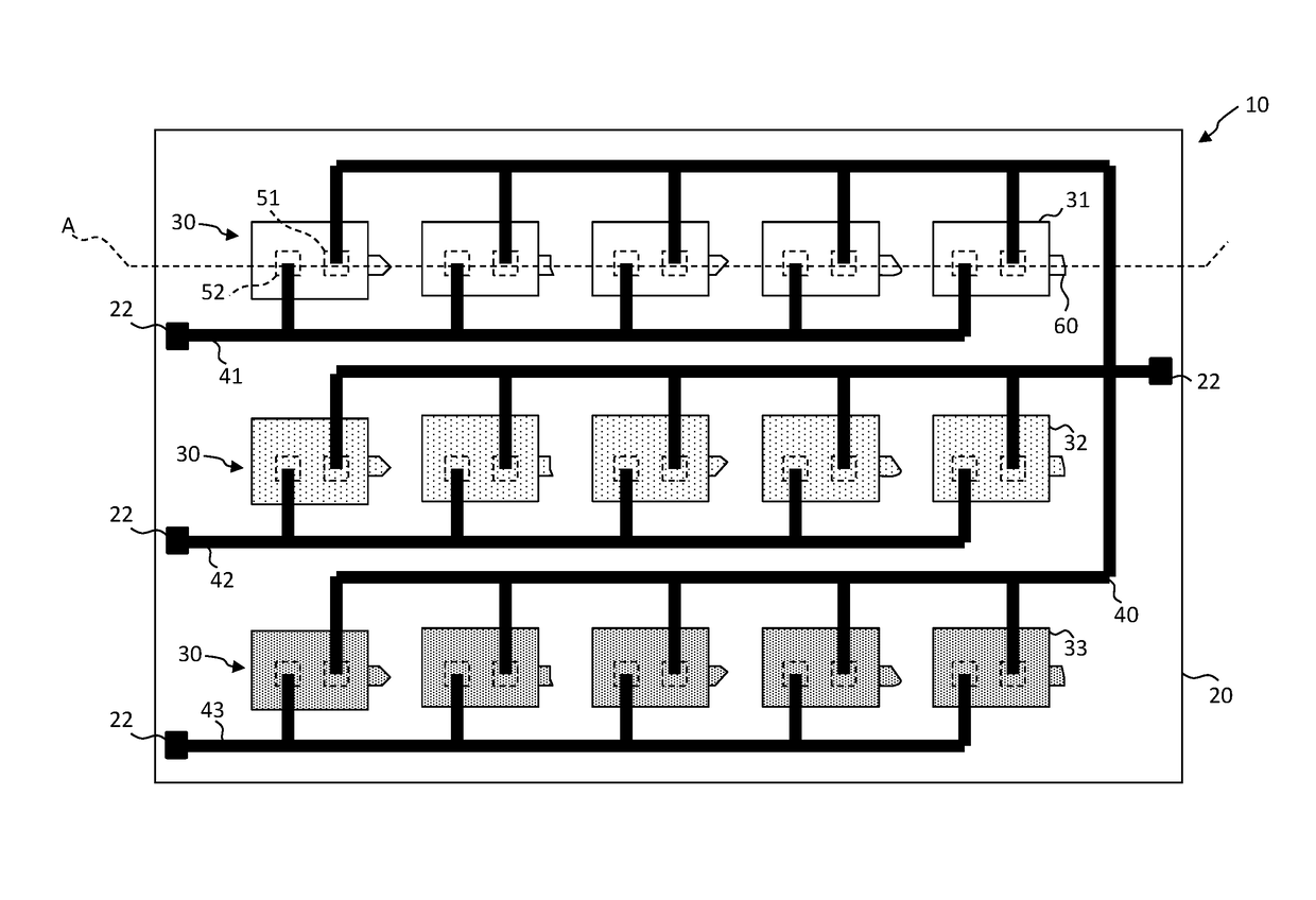
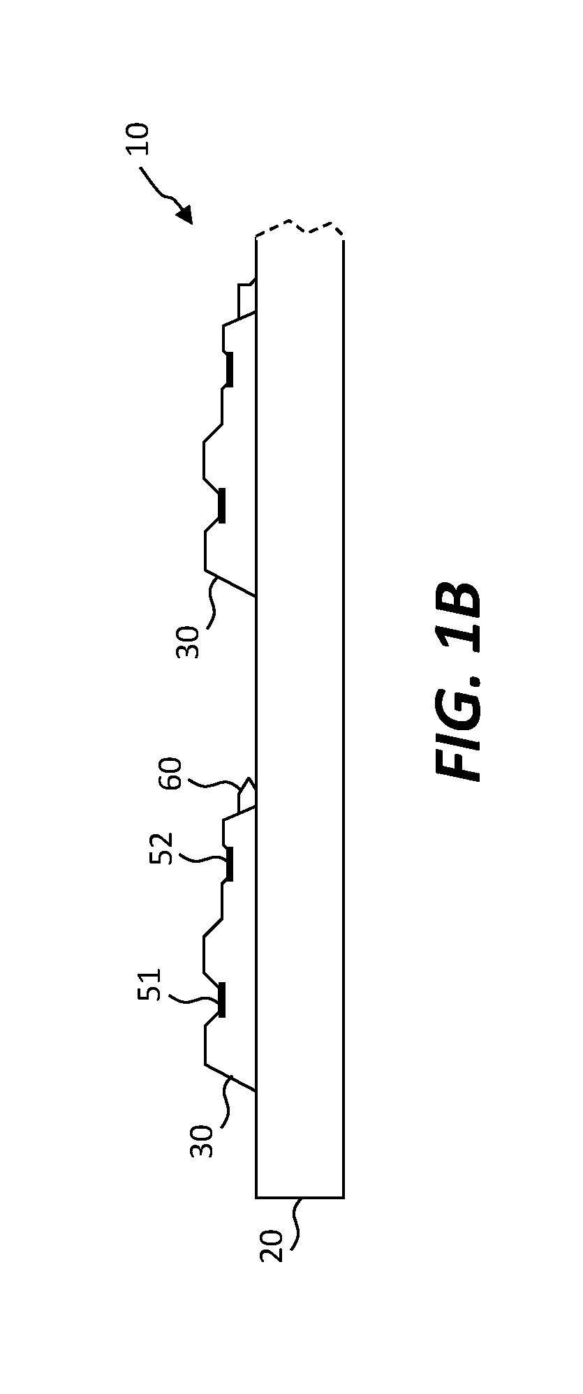
[0040]Referring to the plan view schematic illustration of FIG. 1A and the corresponding partial cross section schematic illustration of FIG. 1B taken along a portion of cross section A of FIG. 1A, in some embodiments of the present invention a multi-LED component 10 includes a component substrate 20 having opposing sides. A common electrode 40, a first electrode 41, and a second electrode 42 are disposed on, in, or over a side of the component substrate 20. A first plurality of first LEDs 31 and a second plurality of second LEDs 32 (collectively ...


PUM


Abstract

A multi-LED component comprises a component substrate comprising a common electrode, a first electrode, a second electrode, a plurality of first LEDs, and a plurality of second LEDs all disposed on the component substrate. Each first LED and each second LED comprises first and second LED contacts for providing power to each corresponding LED to cause the LED to emit light. The first LED contact of each first LED and each second LED is electrically connected to the common electrode. The second LED contacts of the first LEDs are electrically connected to the first electrode. The second LED contacts of the second LEDs are electrically connected to the second electrode so that the first LEDs are electrically connected in parallel and the second LEDs are electrically connected in parallel.

Description

PRIORITY APPLICATION[0001]This application claims the benefit of U.S. Provisional Patent Application No. 62 / 398,007, filed on Sep. 22, 2016, entitled “Multi-LED Component,” the content of which is hereby incorporated by reference herein in its entirety.RELATED APPLICATIONS[0002]Reference is made to U.S. Provisional Patent Application No. 62 / 395,001, filed Sep. 15, 2016, entitled “Electrically Parallel Fused LEDs,” by Bower et al., the content of which is incorporated by reference herein in its entirety.FIELD OF THE INVENTION[0003]The present invention relates to assemblies of inorganic light-emitting diodes electrically connected in parallel.BACKGROUND OF THE INVENTION[0004]Light-emitting diodes (LEDs) are widely used, inter alia, in lamps or other illuminators, as indicators in electronic devices, and in large-format displays. For example, displays using LEDs are found in outdoor signage and stadium displays.[0005]Inorganic light-emitting diode displays using inorganic micro-LEDs o...

Claims


Application Information

Patent Timeline
Patent Type & Authority Patents(United States)
IPC IPC(8): H05B33/08H05B37/02H05B44/00
CPCH05B33/089H05B37/0218H05B33/0872H01L25/0753H05K1/0293H05K3/225H05K2201/09236H05K2201/10181H05B45/46Y02B20/40H05B45/20H05B45/50H01L25/167H05B47/11
Inventor BOWER, CHRISTOPHERTRINDADE, ANTONIO JOSE MARQUESCOK, RONALD S.
Owner X DISPLAY CO TECH LTD
Learn More