
Method of producing optical laminate, optical laminate, polarizing plate and organic el display device

a technology of optical laminates and polarizing plates, applied in the direction of polarising elements, solid-state devices, synthetic resin-layered products, etc., can solve the problems of reducing contrast and reflecting glare, and achieve the effect of suppressing film thickness unevenness

Active Publication Date: 2018-05-22
FUJIFILM CORP
View PDF24 Cites 0 Cited by
  • Summary
  • Abstract
  • Description
  • Claims
  • Application Information

AI Technical Summary

Benefits of technology

The present invention provides an optical laminate with reduced unevenness in the film thickness of the optically anisotropic layer and no visible defects. This is achieved by paying attention to the surface tension of a specific solution containing a fluorine compound. This optical laminate can be used in various applications, such as polarizing plates and organic EL display devices.

Problems solved by technology

For example, since an organic EL display device has a structure in which layers having different refractive indexes are laminated or a structure in which metal electrodes are used, there arises a problem that external light is reflected in the interfaces of each of these layers to cause a reduction in contrast and reflected glare.

Method used

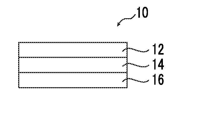
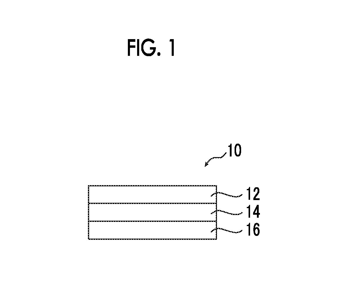
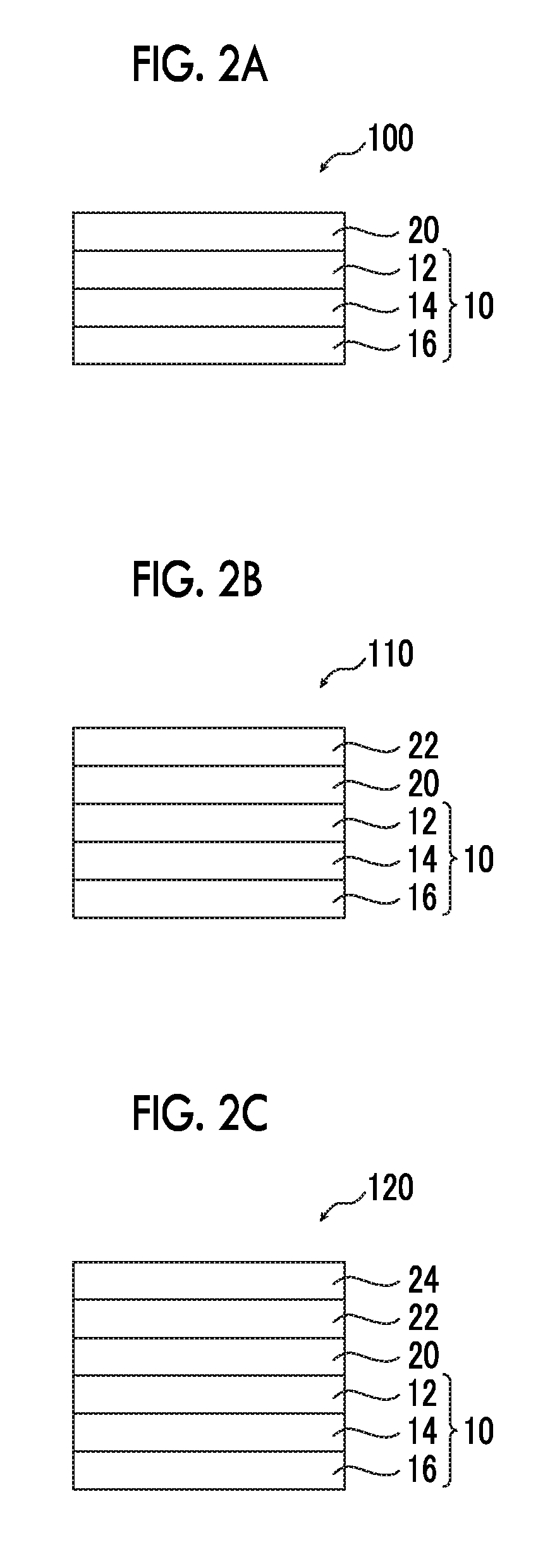

Image

  • Method of producing optical laminate, optical laminate, polarizing plate and organic el display device
  • Method of producing optical laminate, optical laminate, polarizing plate and organic el display device
  • Method of producing optical laminate, optical laminate, polarizing plate and organic el display device

Examples


example 1

[0163]

[0164]The following composition was put into a mixing tank and was stirred while being heated to dissolve the respective components, thereby preparing a cellulose acylate solution A.

[0165]

Composition of Cellulose Acylate Solution ACellulose acetate having a substitution degree of100parts by mass2.86Triphenyl phosphate (plasticizer)7.8parts by massBiphenyl diphenyl phosphate (plasticizer)3.9parts by massMethylene chloride (first solvent)300parts by massMethanol (second solvent)54parts by mass1-Butanol11parts by mass

[0166]The following composition was put into another mixing tank and was stirred while being heated to dissolve the respective components, thereby preparing an additive solution B.

[0167]

Composition of Additive Solution BCompound B1 below (Re lowering agent)40 parts by massCompound B2 below  4 parts by mass(wavelength dispersion controlling agent)Methylene chloride (first solvent)80 parts by massMethanol (second solvent)20 parts by massCompound B1

Compound B2

[0168]40 p...

examples 2 to 4

[0190]Optical laminates were prepared in the same manner as in Example 1 except that in the composition a, instead of using the fluorine compound FP-1, the following fluorine compound FP-3 was used and in the composition b, the amount of the fluorine compound FP-2 added was changed to the amount of addition shown in Table 1 below.

[0191]

examples 5 and 6

[0192]Optical laminates were prepared in the same manner as in Example 1 except that in the composition a, instead of using the fluorine compound FP-1, the fluorine compound FP-2 was used and in the composition b, instead of using the fluorine compound FP-1 and the fluorine compound FP-2, the following fluorine compound FP-4 was incorporated in the amount of addition shown in Table 1 below.

[0193]


PUM

PropertyMeasurementUnit
temperatureaaaaaaaaaa
wavelengthaaaaaaaaaa
angleaaaaaaaaaa

Abstract

The present invention provides an optical laminate which is suppressed in film thickness unevenness of an optically anisotropic layer and is free from point defects, a method of producing the same, and a polarizing plate and an organic EL display device using the optical laminate. The method of producing an optical laminate having an optically anisotropic layer A and an optically anisotropic layer B, includes where the layer A and the layer B are provided in direct contact with each other. The method further includes where both a composition a for forming the layer A and a composition b for forming the layer B contain a fluorine compound, and when the layer A is formed using composition a and layer B is formed using composition b, layer A and layer B are formed in this order under the condition that composition a and composition b satisfy predetermined surface tension relationships.

Description

CROSS-REFERENCE TO RELATED APPLICATIONS[0001]This application is a Continuation of PCT International Application No. PCT / JP2015 / 074086 filed on Aug. 26, 2015, which was published under PCT Article 21(2) in Japanese, and which claims priority under 35 U.S.C. § 119(a) to Japanese Patent Application No. 2014-175874 filed on Aug. 29, 2014. The above applications are hereby expressly incorporated by reference, in their entirety, into the present application.BACKGROUND OF THE INVENTION[0002]1. Field of the Invention[0003]The present invention relates to a method of producing an optical laminate, an optical laminate, a polarizing plate, and an organic EL display device.[0004]2. Description of the Related Art[0005]A phase difference plate has very numerous applications and is already used for a reflective type liquid crystal display (LCD), a semi-transmissive type LCD, a brightness enhancement film, an organic electroluminescence (EL) display device, a touch panel, and the like. For example...

Claims


Application Information

Patent Timeline
Patent Type & Authority Patents(United States)
IPC IPC(8): H01L51/52B32B27/32B32B27/30B32B27/08G02B5/30B32B27/36
CPCG02B5/3016B32B27/30B32B27/306B32B27/32B32B27/365G02B5/305G02B5/3083H01L51/5281B32B27/08B32B2457/206B32B2255/26B32B2270/00B32B2307/416B32B2307/42B32B2307/422B32B2307/706B32B2457/202G02B5/30C09D1/00B32B7/12B32B27/286B32B2255/10B32B2255/28B32B2264/102B32B2307/514C09D133/16C09K19/3852C09D4/06C09D133/14H10K59/8791G02B1/14G02B1/04G02B5/3041H05B33/02B32B7/023H10K50/86
Inventor YOSHIDA, SHINPEISUZUKI, MASAAKIAMEMIYA, KAZUHIROOTANI, TAKETO
Owner FUJIFILM CORP
Learn More