Vacuum pump protection net, method for manufacturing the same, and vacuum pump
a vacuum pump and protection net technology, applied in the direction of machines/engines, liquid fuel engines, positive displacement liquid engines, etc., can solve the problems the damage to the protection net itself and the rotor body, etc., to reduce the suction resistance, ensure the attachment strength, and avoid the effect of increasing the size of the vacuum pump
- Summary
- Abstract
- Description
- Claims
- Application Information
AI Technical Summary
Benefits of technology
Problems solved by technology
Method used
Image
Examples
first embodiment
[0025](Vacuum Pump)
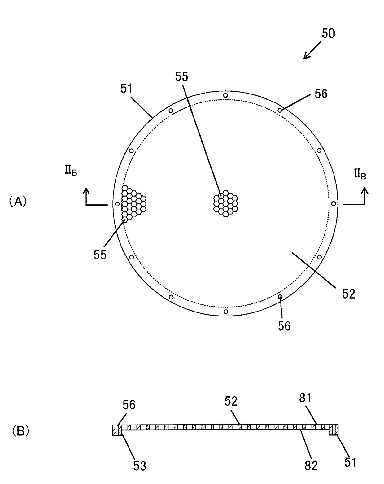
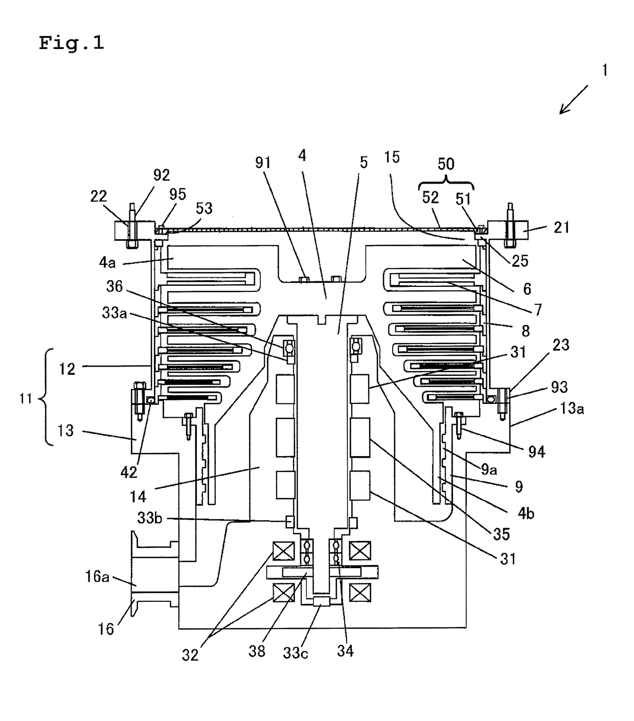
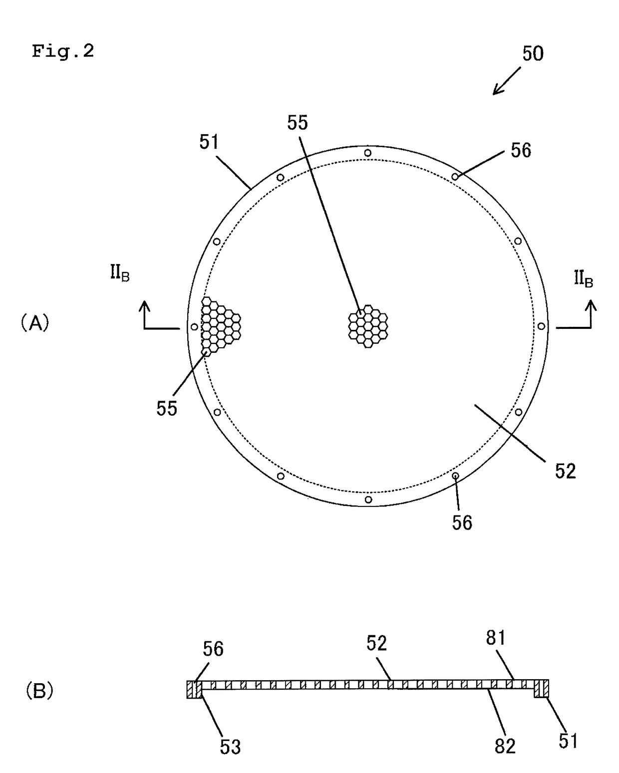
[0026]Hereinbelow, an embodiment of a vacuum pump protection net and a vacuum pump of the present invention will be described with reference to FIGS. 1 to 4(C). FIG. 1 is a cross-sectional view of a turbo-molecular pump as an embodiment of the vacuum pump of the present invention. The turbo-molecular pump 1 is provided with a pump container 11 which includes a case member 12 and a base 13 fixed to the case member 12. The case member 12 has a generally cylindrical shape. The case member 12 is formed of, for example, SUS. An upper flange 21 is formed on an upper end of the case member 12. A circular suction opening 15 is formed on the inner side of the upper flange 21 of the case member 12. The upper flange 21 has bolt insertion through holes 22 which are formed at substantially equal intervals along a circumferential direction. The turbo-molecular pump 1 is attached to an external apparatus, for example, a semiconductor manufacturing apparatus with bolts 92 inserte...
second embodiment
[0049]A second embodiment of the present invention will be described with reference to FIGS. 6(A) to 10. FIG. 6(A) is a plan view of a vacuum pump protection net according to the second embodiment of the present invention. FIG. 6(B) is a cross-sectional view taken along line VIB-VIB in FIG. 6(A). FIG. 7 is an enlarged view of region VII in FIG. 6(A). A protection net 50A of the second embodiment differs from the protection net 50 of the first embodiment in that a reinforcement rib 58 is disposed on a mesh section 52. Hereinbelow, the difference between the second embodiment and the first embodiment will be mainly described. Thus, description of similar points to the first embodiment will not be given by applying identical reference numerals to the corresponding members.
[0050]The reinforcement rib 58 is formed in a cross shape passing through the center of the mesh section 52, and integrally formed with a peripheral edge section 51 and the mesh section 52 using, for example, SUS. A f...
PUM
| Property | Measurement | Unit |
|---|---|---|
| thickness | aaaaa | aaaaa |
| thickness | aaaaa | aaaaa |
| thickness | aaaaa | aaaaa |
Abstract
Description
Claims
Application Information
 - R&D
- Intellectual Property
- Life Sciences
- Materials
- Tech Scout
- Unparalleled Data Quality
- Higher Quality Content
- 60% Fewer Hallucinations
Browse by: Latest US Patents, China's latest patents, Technical Efficacy Thesaurus, Application Domain, Technology Topic, Popular Technical Reports.
© 2025 PatSnap. All rights reserved.Legal|Privacy policy|Modern Slavery Act Transparency Statement|Sitemap|About US| Contact US: help@patsnap.com


