
Golf ball

a golf ball and ball technology, applied in the field of golf balls, can solve the problems of excessive lifting force, insufficient turbulence, and rising of golf balls, and achieve the effect of great flight distan

Active Publication Date: 2018-05-22
SUMITOMO RUBBER IND LTD
View PDF21 Cites 4 Cited by
  • Summary
  • Abstract
  • Description
  • Claims
  • Application Information

AI Technical Summary

Benefits of technology

[0015]In the golf ball according to the present invention, a great flight distance is obtained in a shot with a middle iron. In the golf ball, variations of flight distances in shots with a middle iron are small.

Problems solved by technology

In the polyhedron pattern, the turbulization is insufficient.
If a golf ball having above mentioned improved hemispherically divided pattern is hit with a middle iron, an excessive lift force is generated.
The lift force may cause rising of the golf ball during flight.
The rising impairs flight distance performance.
In other words, the golf ball is inferior in stability of flight distance.
However, the density of dimples in the random pattern is low.
In the pattern, suppression of drag is insufficient.
When the golf ball is hit with a middle iron, great flight distance cannot be achieved.

Method used


Image

  • Golf ball
  • Golf ball
  • Golf ball

Examples


example 1

[0083]A rubber composition was obtained by kneading 100 parts by weight of a high-cis polybutadiene (trade name “BR-730” manufactured by JSR Corporation), 22.5 parts by weight of zinc diacrylate, 5 parts by weight of zinc oxide, 5 parts by weight of barium sulfate, 0.5 parts by weight of diphenyl disulfide, and 0.6 parts by weight of dicumyl peroxide. This rubber composition was placed into a mold including upper and lower mold halves each having a hemispherical cavity, and heated at 170° C. for 18 minutes to obtain a core with a diameter of 38.5 mm.

[0084]A resin composition was obtained by kneading 50 parts by weight of an ionomer resin (trade name “Himilan 1605”, manufactured by Du Pont-MITSUI POLYCHEMICALS Co., Ltd.), 50 parts by weight of another ionomer resin (“Himilan AM7329”, manufactured by Du Pont-MITSUI POLYCHEMICALS Co., Ltd.), and 4 parts by weight of titanium dioxide with a twin-screw kneading extruder. The core was covered with this resin composition by injection moldi...


PUM


Abstract

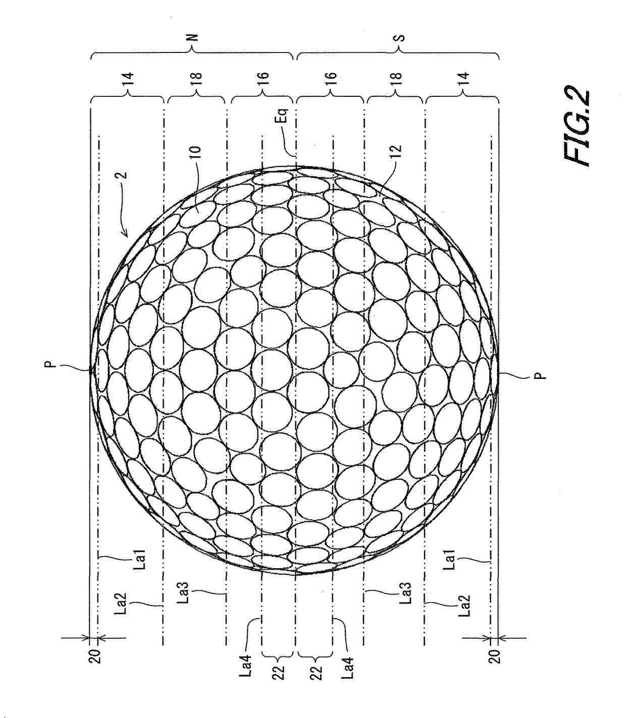
A golf ball 2 includes a large number of dimples 10 on a surface thereof. The surface has a northern hemisphere N and a southern hemisphere S. Each of the hemispheres has a high-latitude region 14, a mid-latitude region 18 and a low-latitude region 16. The high-latitude region 14 has a latitude range of 40° or greater but 90° or less. The mid-latitude region 18 has a latitude range of 20° or greater but less than 40°. The low-latitude region 16 has a latitude range of 0° or greater but less than 20°. The number of planes that can divide a dimple pattern of the hemisphere so that divided dimple patterns are mirror symmetry to each other is one. Neither a dimple pattern of the high-latitude region 14 nor a dimple pattern of the low-latitude region 16 is rotationally symmetrical.

Description

[0001]This application claims priority on Patent Application No. 2014-131995 filed in JAPAN on Jun. 27, 2014. The entire contents of this Japanese Patent Application are hereby incorporated by reference.BACKGROUND OF THE INVENTION[0002]Field of the Invention[0003]The present invention relates to golf balls. Specifically, the present invention relates to improvement of aerodynamic characteristic of golf balls.[0004]Description of the Related Art[0005]Golf balls have a large number of dimples on the surfaces thereof. The dimples disturb the air flow around the golf ball during flight to cause turbulent flow separation. This phenomenon is referred to as “turbulization”. Due to the turbulization, separation points of the air from the golf ball shift backwards leading to a reduction of drag. The turbulization promotes the displacement between the separation point on the upper side and the separation point on the lower side of the golf ball, which results from the backspin, thereby enhanc...

Claims


Application Information

Patent Timeline
Patent Type & Authority Patents(United States)
IPC IPC(8): A63B37/06A63B37/00
CPCA63B37/0006A63B37/002A63B37/0004A63B37/0077A63B37/0017A63B37/0018A63B37/0021A63B37/0016A63B37/00065
Inventor SAJIMA, TAKAHIROMIMURA, KOHEI
Owner SUMITOMO RUBBER IND LTD
Learn More