Camera module and electronic apparatus including conductive housing and feeding coil
a technology of electronic equipment and conductive housing, which is applied in the direction of transformers/inductance coils/windings/connections, inductances, etc., can solve the problems of inability to communicate with a communication partner, considerable reduction in communication distance, and inability to achieve desired communication characteristics. , to achieve the effect of stable communication characteristics
- Summary
- Abstract
- Description
- Claims
- Application Information
AI Technical Summary
Benefits of technology
Problems solved by technology
Method used
Image

Examples
first preferred embodiment
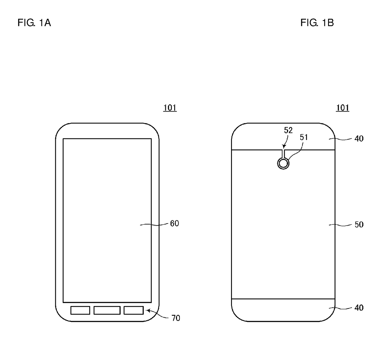
[0040]FIG. 1A is a top (front) view of an electronic apparatus 101 including a camera module according to a first preferred embodiment of the present invention, and FIG. 1B is a bottom (back) view of the electronic apparatus 101. The electronic apparatus 101 is, for example, a cellular phone terminal or a tablet terminal, and includes a circuit for NFC-based communication.
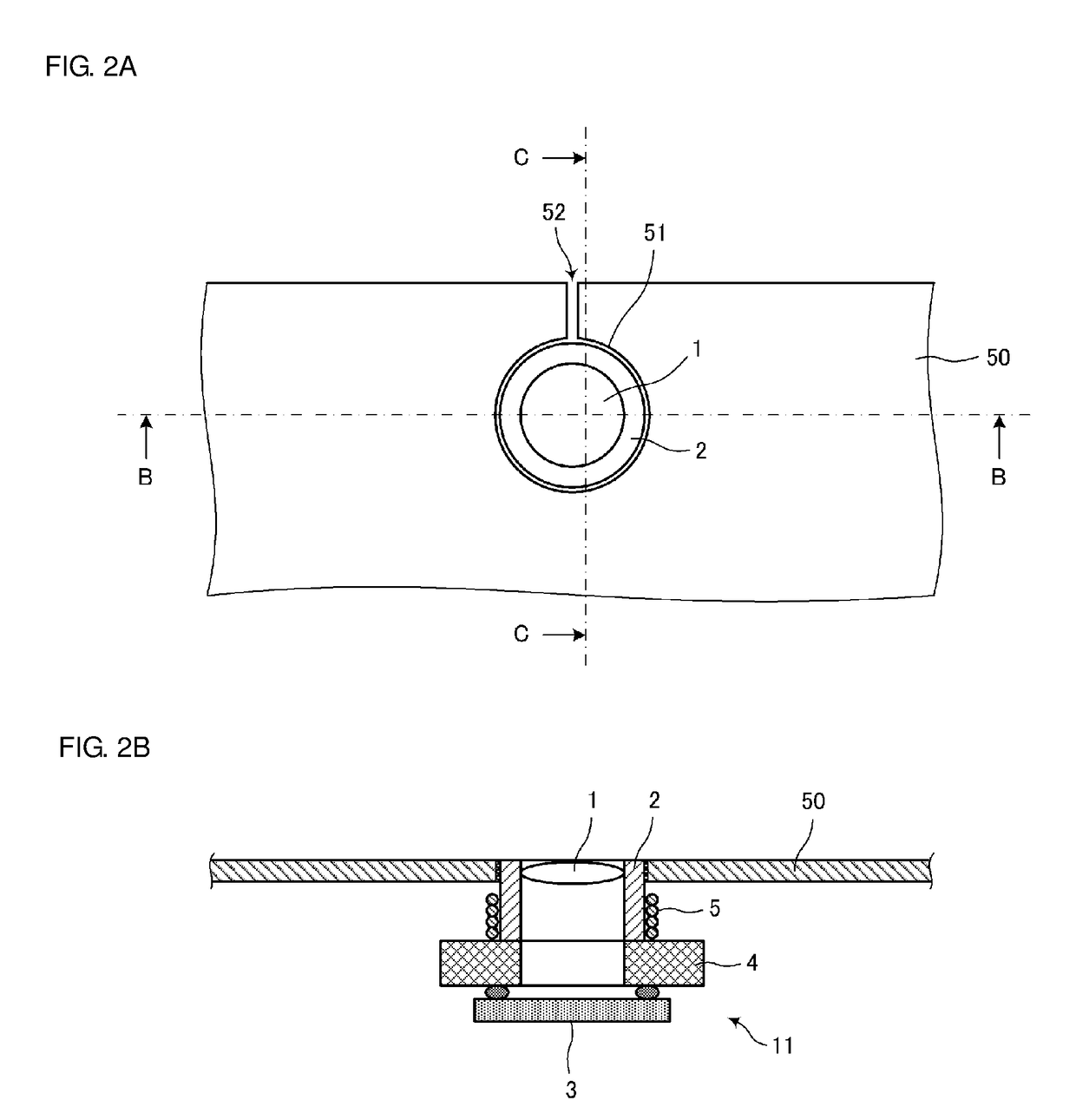
[0041]As illustrated in FIG. 1A, the electronic apparatus 101 includes, on the front side thereof, a display 60, which combines a touch panel with a display panel, and operation buttons 70. As illustrated in FIG. 1B, the electronic apparatus 101 includes a resin housing 40 and a metal housing 50 with conductivity. The metal housing 50 includes an opening 51 and a slit 52. A camera module is disposed in the housing of the electronic apparatus 101, with a lens facing the opening 51. A lens 1 of the camera module is disposed to be exposed from the opening 51. The slit 52 may have a width equal to the diameter of the o...
second preferred embodiment
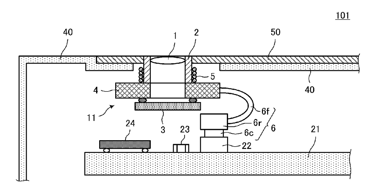
[0051]FIG. 7 is a cross-sectional view illustrating a structure of a camera module according to a second preferred embodiment of the present invention, together with a portion of the metal housing. A camera module 12 includes the lens 1, the lens holder 2 that holds the lens 1, the image sensor 3 that converts an image formed by the lens 1 into an electrical signal, and the substrate 4. The lens holder 2 is provided with the feeding coil 5 wound about the optical axis of the lens 1. The lens holder 2 is further provided with a magnetic member 7 on the inner periphery of the feeding coil 5 (i.e., between the lens holder 2 and the feeding coil 5). That is, the magnetic member 7 is disposed along the outer periphery of the lens holder 2 having a cylindrical shape, and the feeding coil 5 is wound along the outer periphery of the magnetic member 7. The feeding coil 5 and the magnetic member 7 are disposed in the space between the metal housing 50 and the substrate 4. The magnetic member ...
third preferred embodiment
[0053]FIG. 8 is a cross-sectional view illustrating a structure of a camera module according to a third preferred embodiment of the present invention, together with a portion of the metal housing. A camera module 13 includes the lens 1, the lens holder 2, the image sensor 3, and the substrate 4. The lens holder 2 is provided with the feeding coil 5 therearound. The feeding coil 5 is wound about the optical axis of the lens 1. The feeding coil 5 is coated with a cover layer 8 having a low dielectric constant.
[0054]The camera module 13 is held in place, with an end portion of the lens holder 2 inserted in the opening 51 in the metal housing 50. For example, the cover layer 8 is bonded to the inner periphery of the opening 51. Alternatively, the camera module 13 is attached to the circuit board (not shown) in the housing or to the resin housing, and is designed to be brought into the state of FIG. 8 when the metal housing 50 is mounted onto the resin housing 40.
[0055]The feeding coil 5...
PUM
| Property | Measurement | Unit |
|---|---|---|
| conductive | aaaaa | aaaaa |
| optical axis | aaaaa | aaaaa |
| communication distance | aaaaa | aaaaa |
Abstract
Description
Claims
Application Information
 - R&D
- Intellectual Property
- Life Sciences
- Materials
- Tech Scout
- Unparalleled Data Quality
- Higher Quality Content
- 60% Fewer Hallucinations
Browse by: Latest US Patents, China's latest patents, Technical Efficacy Thesaurus, Application Domain, Technology Topic, Popular Technical Reports.
© 2025 PatSnap. All rights reserved.Legal|Privacy policy|Modern Slavery Act Transparency Statement|Sitemap|About US| Contact US: help@patsnap.com