Printing apparatus

a printing apparatus and printing medium technology, applied in printing, typewriters, textiles and paper, etc., can solve the problems of difficult to provide the printing apparatus with excellent images, difficult to provide the laser irradiation device on the printing apparatus, and unclear images, so as to prevent the texture of the printing medium and reduce the image quality

Active Publication Date: 2018-05-01
SEIKO EPSON CORP
View PDF15 Cites 5 Cited by
  • Summary
  • Abstract
  • Description
  • Claims
  • Application Information

AI Technical Summary

Benefits of technology

[0008]According to the present application example, the printing apparatus includes the fluff cutter portion which cuts the fluff of the printing medium. Opportunity of the contact between the discharging head and the printing medium with each other is reduced and defects such as nozzle missing and landing deviation which are generated by contact between the discharging head and the fluff with each other are less likely to be generated, by the fluff of the printing medium transported by a transport unit being cut in a predetermined height by the fluff cutter portion, according to the printing condition input to the input unit by a user. In addition, the discharging head can be set low, by cutting the fluff. Therefore, images having excellent printing quality are formed on the printing medium on which the fluff is generated. Therefore, the printing apparatus which improves the printing quality can be provided.Application Example 2
[0018]According to the application example, the printing apparatus can prevent texture of the printing medium from being damaged by the cutting of the fluff or printing of which the image quality is reduced from being performed, in advance, by including the notifying portion which notifies the alarm in a case where a relationship between the distance between the printing medium and the discharging head and the type of the printing medium is inappropriate, for example.

Problems solved by technology

However, providing the laser irradiating device on a printing apparatus is difficult due to increase in cost and safety issues of the apparatus.
In addition, there is a problem that images are unclear by landing deviation of droplets being increased, in a case where printing is performed in a state a discharging head is raised with respect to a printing medium so that the fluff and the discharging head are not in contact with each other.
Therefore, it is still difficult to provide the printing apparatus which forms images having excellent printing quality on the printing medium on which the fluff is generated.

Method used


Image

  • Printing apparatus
  • Printing apparatus
  • Printing apparatus

Examples


embodiment 1

Schematic Configuration of Printing Apparatus

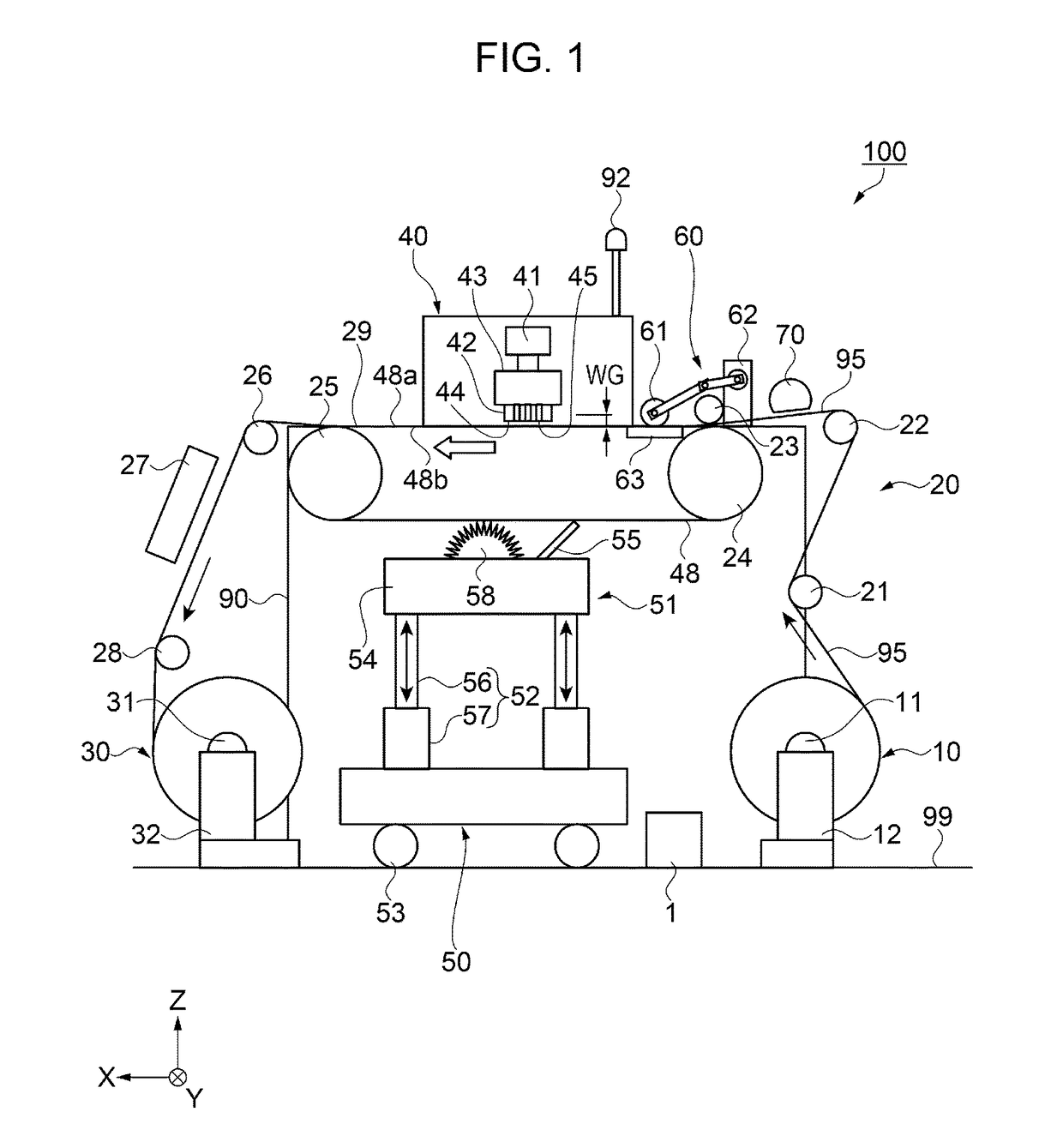
[0030]FIG. 1 is a schematic view illustrating overall configuration of a printing apparatus according to Embodiment 1. First, with reference to FIG. 1, the schematic configuration of the printing apparatus 100 according to the embodiment will be described. In the embodiment, an ink jet type of a printing apparatus 100 which performs printing on a printing medium 95 by forming an image or the like on the printing medium 95 will be described.

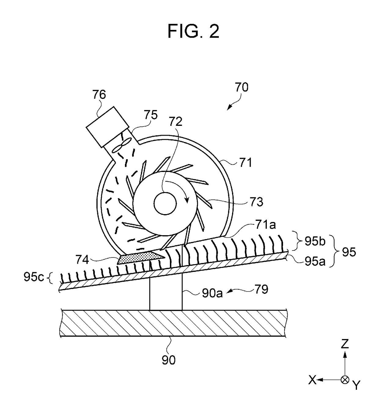
[0031]As illustrated in FIG. 1, the printing apparatus 100 includes a medium transport portion 20, a fluff cutter portion 70, a medium close contacting portion 60, a printing portion 40, a drying unit 27, a cleaning unit 50, and a notifying portion 92. The printing apparatus 100 includes a control portion 1 which controls each portion described above. Each portion of the printing apparatus 100 is attached to a frame portion 90.

[0032]The medium transport portion 20 is a transport unit which transports th...

embodiment 2

[0084]FIG. 7 is a sectional view illustrating configuration of a fluff cutter portion and a projecting portion according to Embodiment 2. FIG. 8 is a side view illustrating configuration of the fluff cutter portion and the projecting portion. Next, with reference to FIG. 7 and FIG. 8, a printing apparatus 200 of the embodiment will be described. For the same components as in Embodiment 1, the same number is used, and a duplicate description thereof will be omitted.

[0085]As illustrated in FIG. 7 and FIG. 8, the printing apparatus 200 includes a projecting portion 80 which lifts the printing medium 95 to a position facing the fluff cutter portion 70. The projecting portion 80 has a plate-like rectangular parallelepiped which is longer than the width of the printing medium 95 in a side view from X axis direction and a top surface (surface of +Z-axis side) of a rectangular parallelepiped is chamfered in an arc shape in a side view from the Y axis direction. The printing medium 95 which ...


PUM


Abstract

A printing apparatus includes a discharging head which discharges liquid on a printing medium mounted on an endless belt; a medium transport portion as a transport unit which transports the printing medium; an input device as an input unit to which printing condition is input; and a fluff cutter portion which is provided on an upstream side of the discharging head in the transport direction and which cuts fluff of the printing medium in a predetermined height according to the printing condition.

Description

BACKGROUND[0001]1. Technical Field[0002]The present invention relates to a printing apparatus.[0003]2. Related Art[0004]In the related art, an ink jet type of a printing apparatus is used which prints an image or the like on a printing medium by discharging liquid such as ink in droplet form from a discharging head having a nozzle toward a surface of the printing medium. It is desirable to process fluff just before printing so that reduction of printing quality by contact between the fluff and the discharging head with each other or attachment of a released fluff to the discharging head is prevented in advance, in a case where fabric of which the fluff is generated on a surface, or the like is used as the printing medium of the printing apparatus. A method for processing the fluff is disclosed in JP-A-2007-224436, for example, which is a method for thermally fusing a fluff layer by radiating a laser beam to the fluff layer.[0005]A fluff processing described in JP-A-2007-224436 requi...

Claims


Application Information

Patent Timeline
Patent Type & Authority Patents(United States)
IPC IPC(8): B41J11/66B41J3/407B41J11/00B41J11/70B41J15/04D06C27/00
CPCB41J11/70B41J3/4078B41J11/0015D06C27/00B41J15/048B41J2/01B41J11/66D06C13/00
Inventor MITSUO, NORITAKA
Owner SEIKO EPSON CORP
Why Eureka
Try Eureka