
Lever-type electrical connector body and related electrical connector assembly

Active Publication Date: 2018-04-17
PHOENIX CONTACT DEVMENT & MFG
View PDF18 Cites 2 Cited by
  • Summary
  • Abstract
  • Description
  • Claims
  • Application Information

AI Technical Summary

Benefits of technology

The patent is about a lever connector assembly that has specific designs for its cam plates to improve separation of electrical connectors. The cam profiles can make the initial rotation of the lever slow and then accelerate for faster separation. Another design provides a constant rate of separation for a constant angular velocity. The lever and its cam plates are designed to fully disengage the electrical connectors but only partially disengage the connector bodies when used to separate the connector assembly. The lever in the opened position is easy to hold and apply force to for complete mechanical separation of the connector assembly.

Problems solved by technology

As a result, the lever construction and the mounting of the lever on the first connector body is relatively complex.
But separating the manually joined connector bodies can be more difficult.
Over time, the force required to disengage the sets of electrical connectors may increase due to environmental effects or corrosion.
Due to the restricted access caused by such close spacing, it is often difficult to manually separate the connector bodies for maintenance or replacement.
But the force required to initially separate the bodies may be high, making separation difficult even with a handle.

Method used


Image

  • Lever-type electrical connector body and related electrical connector assembly
  • Lever-type electrical connector body and related electrical connector assembly
  • Lever-type electrical connector body and related electrical connector assembly

Examples


Embodiment Construction

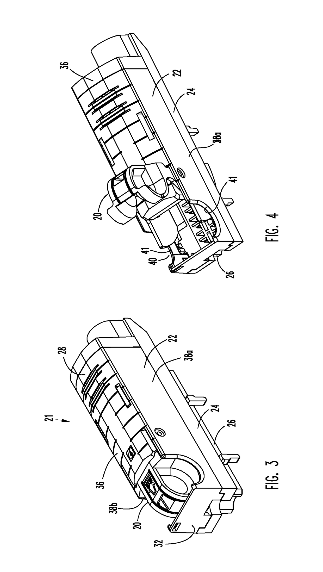
[0028]FIGS. 1 and 2 illustrate a first embodiment electrical connector assembly 10 that includes a first electrical connector body 12 and a second electrical connector body 14. The first and second connector bodies 12, 14 are shown in FIG. 1 engaged with one another to form electrical connections between respective sets of electrical connectors 16, 18 (shown schematically in dotted lines) carried by the first and second connector bodies 12, 14 respectively.

[0029]In the illustrated embodiment the set of electrical connectors 16 is a terminal block having electric terminals and the set of electrical connectors 18 are corresponding pins configured to be received in the terminal block. It is understood that the illustrated sets of electrical connectors are non-limiting and other compatible male and female sets of electrical connectors can be carried in the connector bodies (the terms “male” and “female” referring to compatible sets of electrical connectors intended to inter-engage with ...


PUM


Abstract

A lever-releasable first electrical connector body includes a housing that includes a set of electrical connectors and a lever rotatably mounted in the housing for rotation between retracted and extended positions. When the first connector body is engaged with a second electrical connector body to form electrical connections with the set of electrical connectors, the lever is normally in the retracted position. Rotation of the lever to the extended position causes an end of the lever to engage and urge the second electrical connector away from the first electrical connector.

Description

FIELD OF THE DISCLOSURE[0001]The disclosure relates generally to electrical connector assemblies in which a first electrical connector body housing a set of male or female electrical connectors engages a second electrical connector body housing a corresponding set of the other of the male or female electrical connectors for forming electrical connections between the sets of electrical connectors.BACKGROUND OF THE DISCLOSURE[0002]Lever-type electrical connector assemblies having a first electrical connector body, a second electrical connector body, and a lever mounted on the first electrical connector body are known. The lever moves in a first direction while connecting the first and second electrical connector bodies so that the lever engages the second electrical connector body and draws the connector bodies together for electrically connecting sets of electrical connectors housed in the bodies. The lever moves in the opposite second direction to force the connector bodies apart fo...

Claims


Application Information

Patent Timeline
IPC IPC(8): H01R13/62H01R13/502H01R13/633H01R13/629
CPCH01R13/6335H01R13/502H01R13/62933H01R13/633H01R24/20H01R2107/00
Inventor FAULKNER, SCOTT ANTHONY
Owner PHOENIX CONTACT DEVMENT & MFG
Learn More