
Illumination device

a technology of a diffraction device and a diffraction device, which is applied in the direction of static indicating devices, lighting and heating apparatuses, instruments, etc., can solve the problems of requiring much smaller optical components for step and repeat processes, and achieve the effects of reducing alignment problems, high diffraction efficiency, and constant diffraction efficiency

Active Publication Date: 2018-03-27
SEEREAL TECHNOLOGIES
View PDF7 Cites 4 Cited by
  • Summary
  • Abstract
  • Description
  • Claims
  • Application Information

AI Technical Summary

Benefits of technology

The invention is a flat illumination device that uses a simple and cost-efficient design with only a few optical elements. The device can be created under minor expenses. The device has a modified phase distribution that can be combined with the amplitude distribution, which is used within the same plane of the light source. This allows for the use of an attenuated phase shift mask to tailor the coherence and homogenize the intensity distribution of the exit plane of the illumination device. This results in a complex valued filter function that requires optimization. Overall, the invention provides an efficient and cost-effective solution for creating a flat illumination device with a complex and homogenized lighting effect.

Problems solved by technology

However, step and repeat processes require much smaller optical components only.

Method used


Image

  • Illumination device
  • Illumination device
  • Illumination device

Examples


example

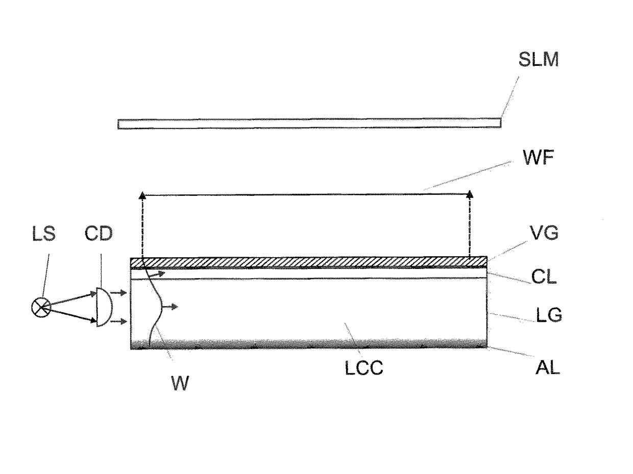
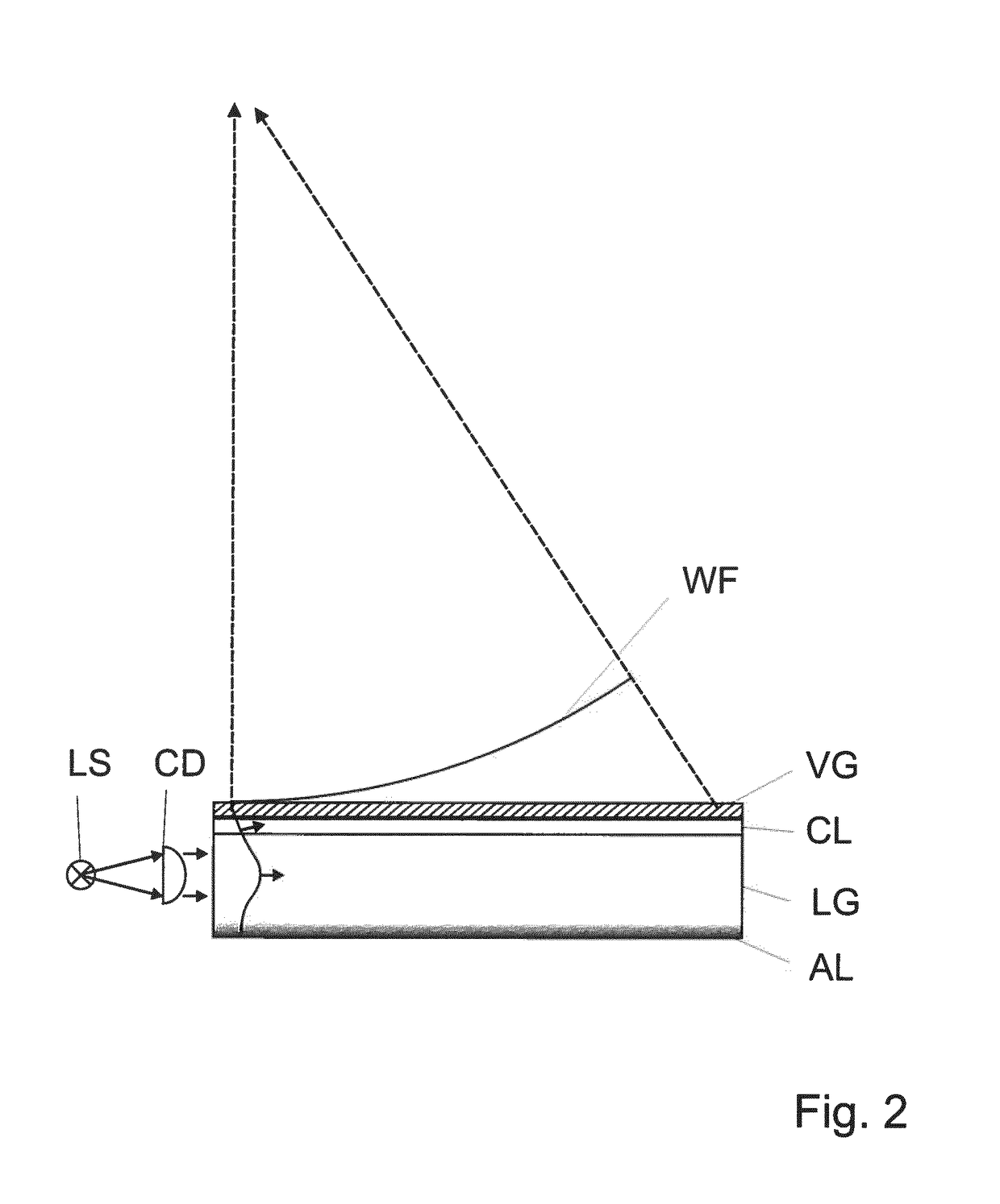
[0640]If single Gauss modes are used than the beam waist can be placed at the centre of the illumination plate. This means that the collimation unit slightly focus the light along one direction.

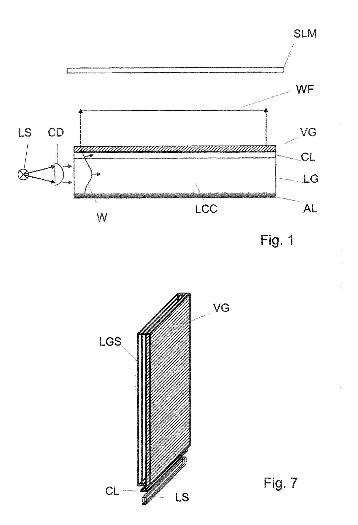
[0641]The collimated light, which propagates within a e.g. PMMA or PC plate, is coupled out segment wise in order to illuminate the complex valued type SLM, which can be termed as C-SLM or P+A-SLM. The P+A-SLM has to be illuminated in a way to avoid functional and thus recognizable gaps. If the SLM uses colour allocated stripes or columns than the decoupling and redirecting of the light can be done stripe wise. The decoupling stripes are related to optional colour filter. Please note that colour filters are not a must here. Patterned RGB decoupling can manage spatial allocated RGB operation of the SLM.

[0642]A segment type embodiment can be realized by using a step and repeat process, which can be established with reasonable low capital expenditure (CAPEX). That is why step and repeat or scann...


PUM


Abstract

An illumination device for illuminating at least one spatial light modulator device. At least one light source device with at least one light source illuminates the at least one spatial light modulator device; a light guiding element through which light emanating from the light source propagates; and at least one light decoupling element arranged on top or inside of the light guiding element. The at least one light decoupling element decouples of a wave field of the light which propagating in the light guiding element into the direction of the spatial light modulator device. The light guiding element has a refractive index which is lower than or at least equal to the refractive index of the at least one light decoupling element. The entrance angle of the wave field entering the light decoupling element is determined by the difference between the refractive indices according to a particular equation.

Description

CROSS REFERENCE TO RELATED APPLICATIONS[0001]This application claims the priority of PCT / EP2013 / 072339, filed on Oct. 24, 2013, which claims priority to EP Application No. 12189852.2, filed on Oct. 24, 2012, and EP Application No, 13161823.3, filed on Mar. 28, 2013, the entire contents of each of which are incorporated fully herein by reference.BACKGROUND OF THE INVENTION[0002]The present invention relates to an illumination device for illuminating at least one spatial light modulator device being used preferably for displaying two-dimensional and / or three-dimensional images comprising at least one light source device with at least one light source for illuminating the at least one spatial light modulator device, a preferably substantially planar light guiding element comprising a light conducting core, where the at least one light source device is arranged on a side of the light guiding element and where the light emanating from at least one light source of the at least one light s...

Claims


Application Information

Patent Timeline
Patent Type & Authority Patents(United States)
IPC IPC(8): F21V7/04G02B6/02F21V8/00G02B27/22H05B37/02
CPCG02B6/005G02B6/0023G02B6/0031G02B6/0068G02B6/02057G02B27/22H05B37/0218G02B6/0076G02B6/0025Y02B20/40G02B30/33G09G3/3473G09G3/003G09G3/3413F21S2/005H05B47/11
Inventor FUTTERER, GERALD
Owner SEEREAL TECHNOLOGIES
Learn More