
Systems and methods for facilitating remote security threat detection

a technology of remote security and detection methods, applied in the field of systems and methods for detecting security threats, can solve the problems of time delay, unnecessary delays for both screening operators and individuals, and the ineffective implementation of such a system can be difficult, so as to achieve convenient insertion, eliminate geographic limitations, and facilitate the effect of connection

Active Publication Date: 2018-03-20
MICHAEL STAPLETON ASSOC LTD
View PDF30 Cites 0 Cited by
  • Summary
  • Abstract
  • Description
  • Claims
  • Application Information

AI Technical Summary

Benefits of technology

The patent describes a threat detection system that allows local operators to send requests to remote experts for assistance in resolving potential security threats. The system organizes remote experts into different groups for handling specific types of requests and dialing plans are used to determine how requests should be allocated to the experts groups. The system is scalable and can easily integrate new experts and expert groups into the system framework. The technical effects of this invention are that it enables real-time communication and interaction between operators and experts, reduces scalability issues, and allows for the easy assimilation of remote experts.

Problems solved by technology

Concert venues, sports stadiums and other highly populated locations or high risk environments pose particular concerns given the extensive harm that may be inflicted in the event that a security threat goes undetected.
However, if a screening device operator is unable to determine whether a particular item presents a security threat, the operator may contact the remotely located expert for assistance in evaluating the item.
Although the configuration of the threat detection system described above has many advantages, effectively implementing such a system can be difficult for several reasons.
The fact that the experts are located remotely from the individuals who are operating the screening devices can create a time delay, with respect to both establishing a connection with the expert and assessing whether a suspicious item poses a security threat.
Failure to ensure that all requests are handled appropriately could create dangerous situations (e.g., in the case that a screening operator believes that an item is bomb or a gun) and may cause unnecessary delays for both the screening operators and individuals at the screening locations who are waiting to be inspected.
Furthermore, after a remote expert has accepted a request for assistance, the remote expert may not be able to resolve the request and may desire the assistance of a second remote expert.
Unfortunately, conventional threat detection systems do not enable a remote expert assigned to a request to communicate with other remote experts in an efficient manner in order to resolve the request.
Another problem associated with conventional network-based threat detection systems is that these systems require all of the remote experts to be located at a single operations center in order to perform their duties.
Requiring the remote experts to be physically present at the operations center can impose serious limitations on the scalability of the system and the ability of the system to service a growing number of customers or screening locations.
For example, if all of the remote experts were required to be located at a single operations center, this may reduce the number of qualified remote experts that can be retained to provide assistance (e.g., since the remote experts must be located within traveling distance of the operations center).
In addition, this prevents other third-party remote experts (e.g., remote experts who are employed by a customer or at a screening location) to be assimilated into the threat detection system.

Method used


Image

  • Systems and methods for facilitating remote security threat detection
  • Systems and methods for facilitating remote security threat detection
  • Systems and methods for facilitating remote security threat detection

Examples


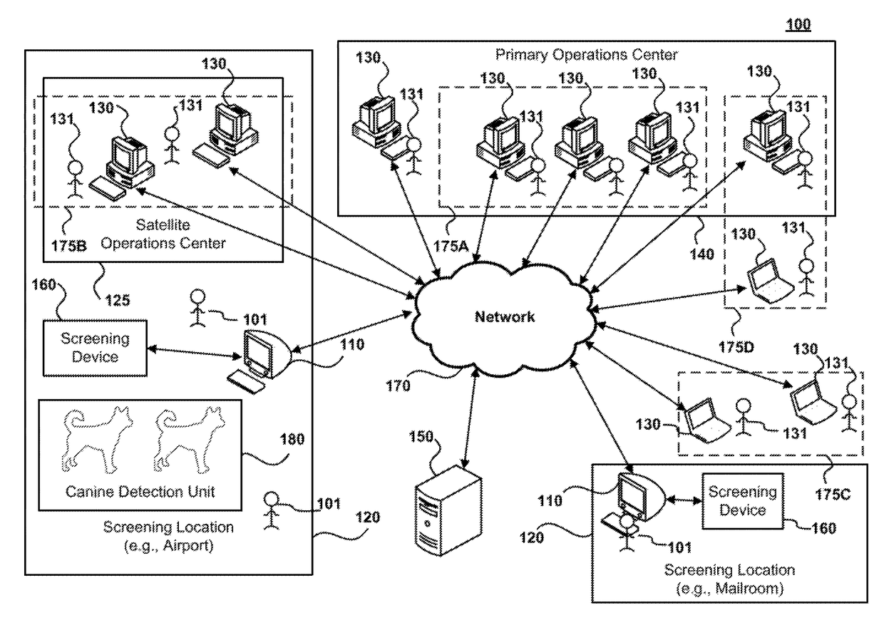
Embodiment Construction

[0039]In the following description, reference is made to the accompanying drawings that form a part hereof, and in which is shown by way of illustration specific embodiments in which the invention may be practiced. It is to be understood that other embodiments may be utilized and structural changes may be made without departing from the scope of the present invention.

[0040]A threat detection system is disclosed for analyzing and detecting security threats at one or more screening locations (e.g., airports, seaports, Customs checkpoints, mailrooms, security checkpoints, stadiums and other venues or high-risk environments). Canine detection units may inspect items or packages at the screening locations. Each canine detection unit may include or more canines that have been trained to detect whether an item (e.g., cargo, bags, packages, luggage, mail, shipment containers or other items) is or contains a security threat. Screening devices at the screening locations may be utilized to fur...


PUM


Abstract

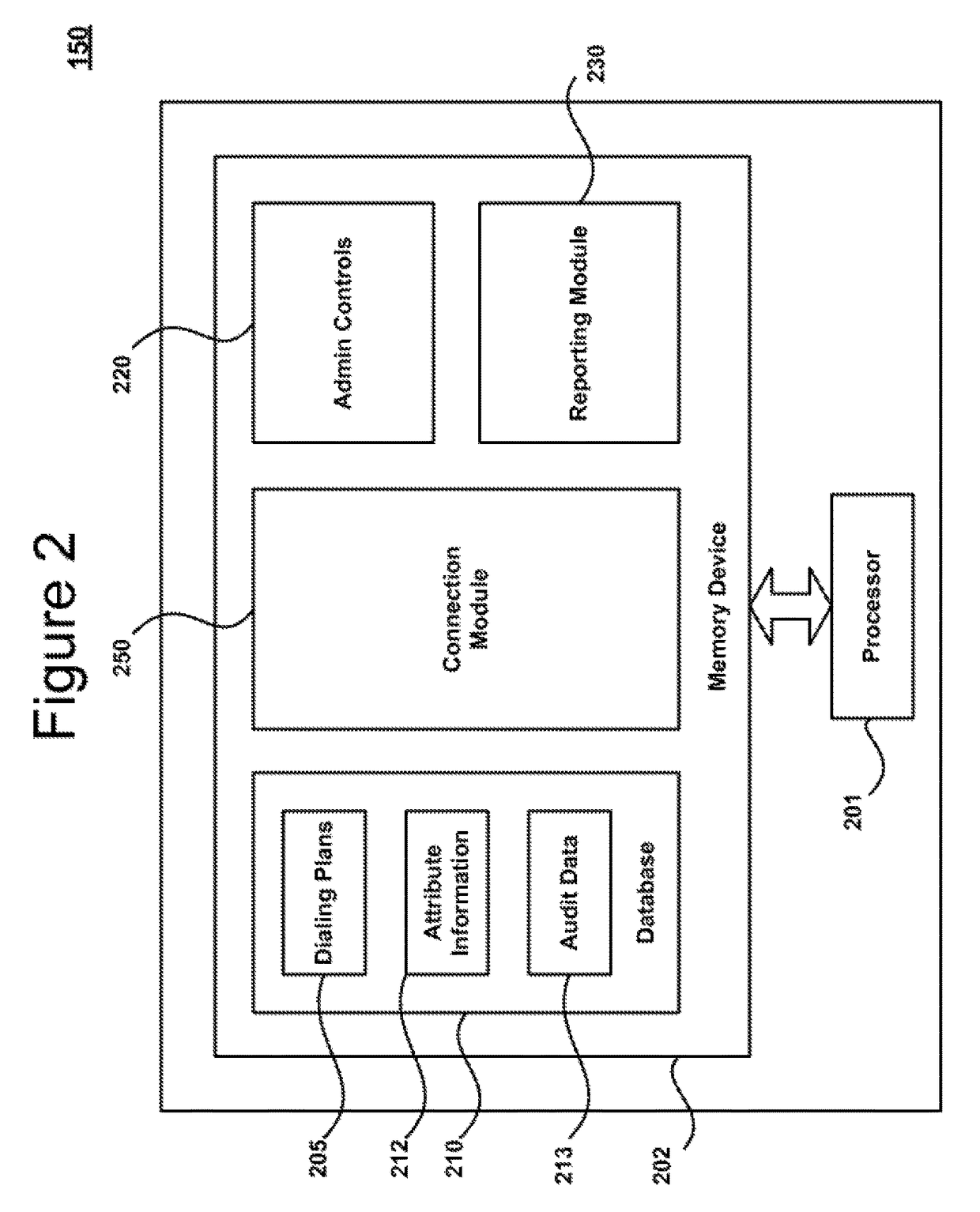
Systems and methods are disclosed for detecting security threats in a network environment. A canine detection unit may initially inspect items at a screening location. A local workstation is used to further inspect the items that are identified as raising potential security concerns. Requests for assistance are submitted to remote experts for assistance with resolving the potential security concerns. One or more servers receive the requests over a network and retrieve dialing plans associated with the origins of the requests. The one or more servers utilize the dialing plans to route the requests to expert groups assigned to dialing plans. In response to the requests being accepted by remote expert devices in one of the expert groups, the one or more servers establish connections between the local workstations and the remote expert devices that accept the requests.

Description

CROSS-REFERENCE TO RELATED APPLICATIONS[0001]The present application claims benefit to and is a continuation-in-part of U.S. patent application Ser. No. 14 / 567,312 filed on Dec. 11, 2014, which is a continuation-in-part of U.S. patent application Ser. No. 14 / 064,100 filed on Oct. 25, 2013. U.S. patent application Ser. No. 14 / 567,312 also claims the benefit of U.S. Provisional Application No. 61 / 914,777 filed on Dec. 11, 2013. All of these applications are incorporated herein by reference in their entireties.COPYRIGHT NOTICE[0002]A portion of the disclosure of this patent document contains material, which is subject to copyright protection. The copyright owner has no objection to the facsimile reproduction by anyone of the patent document or the patent disclosure, as it appears in the Patent and Trademark Office patent files or records, but otherwise reserves all copyright rights whatsoever.FIELD OF THE INVENTION[0003]The present principles are directed to systems and methods for det...

Claims


Application Information

Patent Timeline
Patent Type & Authority Patents(United States)
IPC IPC(8): H04L29/06G06Q50/26
CPCG06Q50/265H04L63/20H04L63/1441H04L63/1408
Inventor CROWLEY, RAYMONDWYNN, MICHAELATHERALL, JOEDIMMICK, MATTHEW RYAN
Owner MICHAEL STAPLETON ASSOC LTD
Learn More