
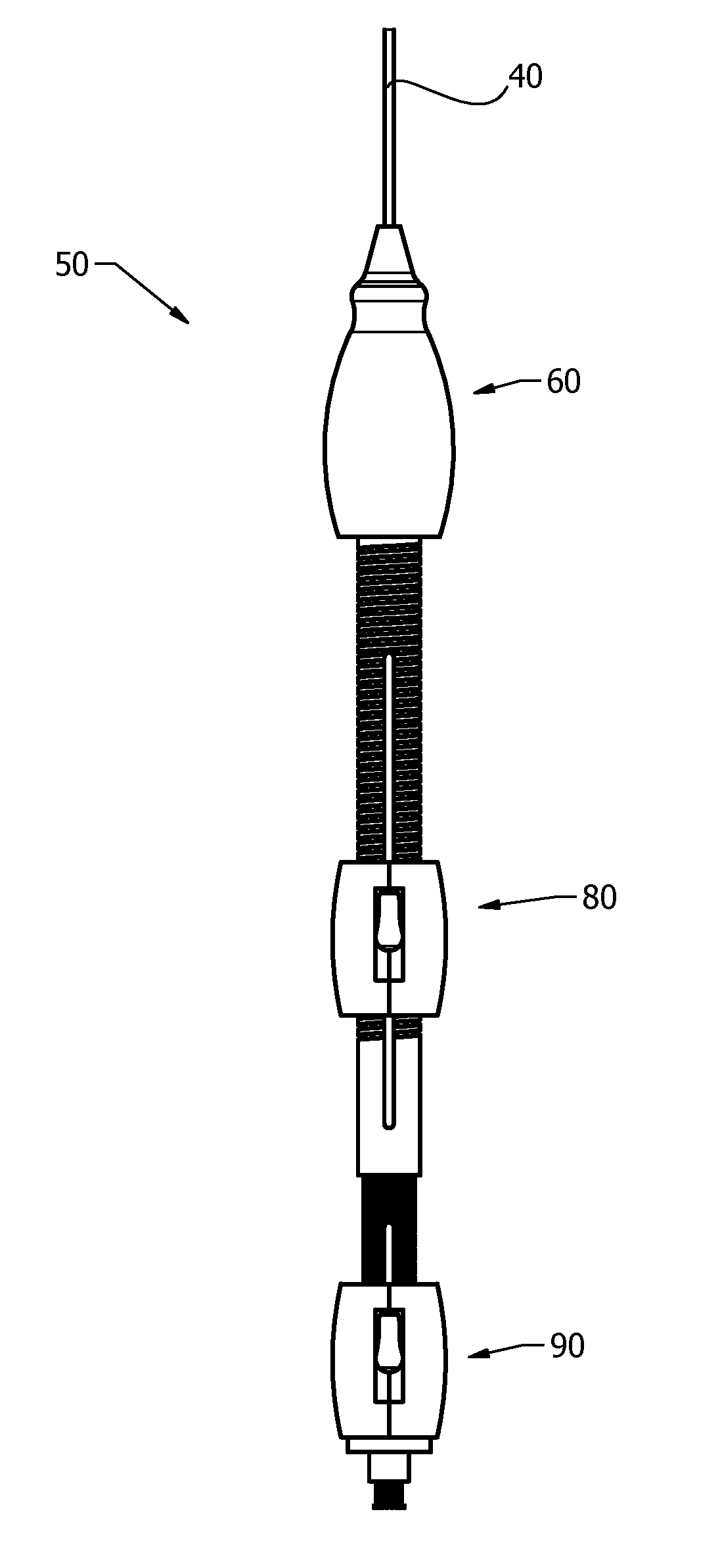
Integrated catheter guide wire control device

a control device and guide wire technology, applied in the field of integrated catheter guide wire control devices, can solve the problems of limited stent deployment precision, marked challenges in transcatheter valve replacement, and malposition of stents, so as to facilitate a change of orientation, reduce fatigue of surgeons, and improve the location accuracy of catheter delivery medical devices

Active Publication Date: 2018-03-20
RING MICHAEL
View PDF5 Cites 21 Cited by
  • Summary
  • Abstract
  • Description
  • Claims
  • Application Information

AI Technical Summary

Benefits of technology

The solution enhances the precision and accuracy of prosthetic valve deployment, reducing the risk of malposition and improving the overall efficiency of transcatheter valve replacement procedures by providing better control over the guide wire and delivery capsule orientation.

Problems solved by technology

A well-known issue with self-expanding nitinol stents is their tendency to “jump” as the sheath on the delivery catheter is retracted, which limits the precision of the stent deployment and can result in malposition of the stent.
Transcatheter valve replacement presents marked challenges over other endovascular procedures that utilize a catheter.
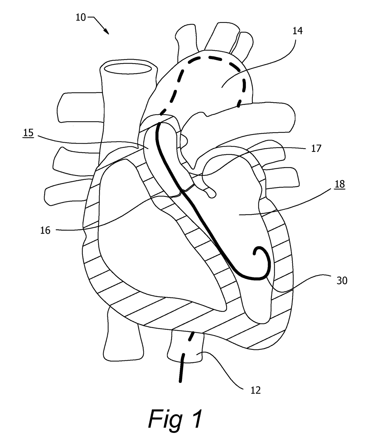
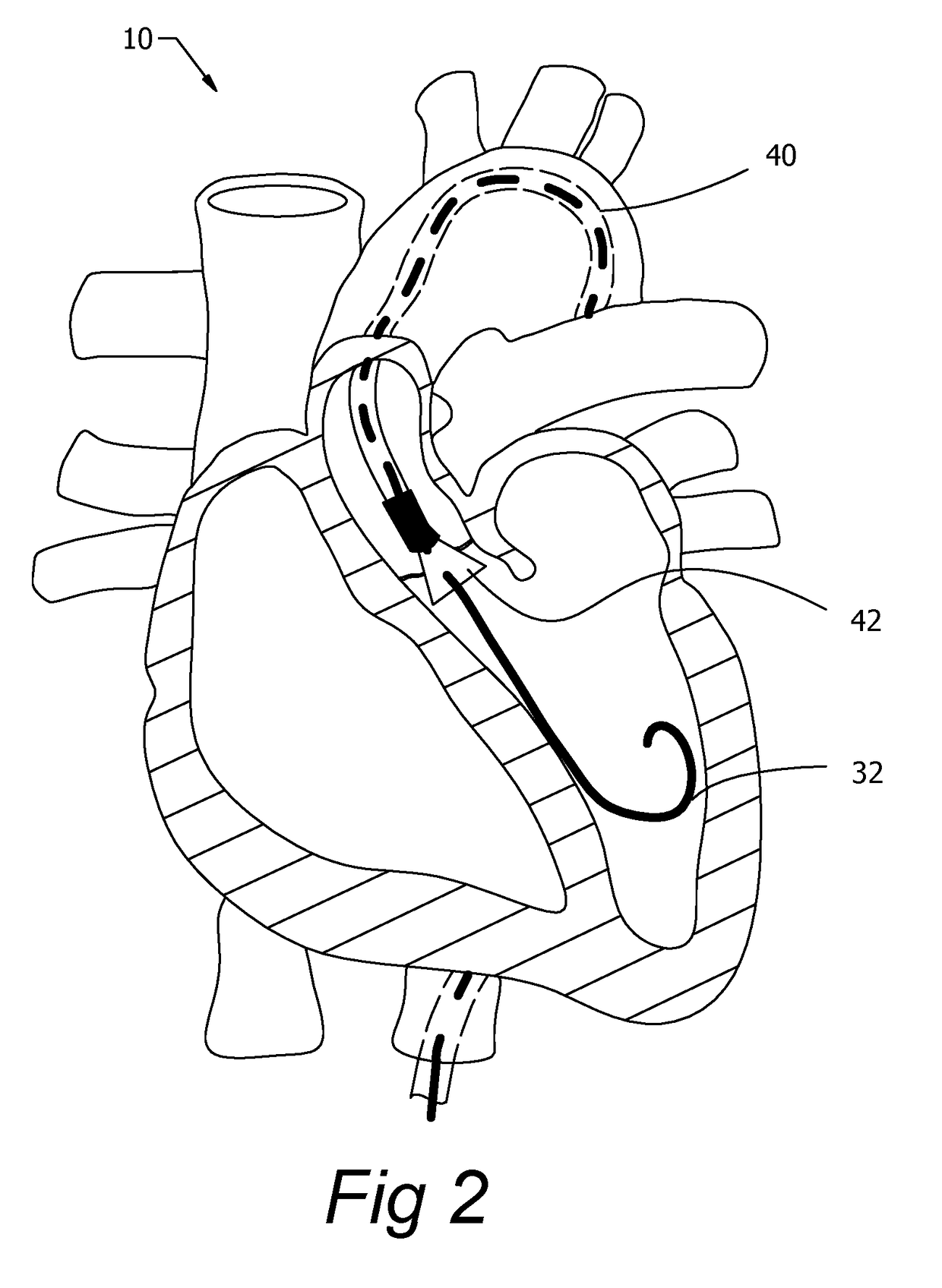
Unlike typical endovascular procedures which occur in constrained tubular blood vessels where there is limited spatial movement of the devices, transcatheter valve procedures by their nature are performed in the heart with relatively large and spatially complicated chambers that pose significant challenges to guidewire management and device manipulation by the surgeon.
An improperly deployed valve can lead to perivalvular regurgitation or catastrophic embolization of the device into either the heart or aorta.
With guide wires being small in diameter, often coated in low friction materials, and with bodily fluids present, maintaining optimal pressure on the guide wire throughout the valve replacement procedure can be challenging and fatiguing for the surgeon.
Although the field of transcatheter mitral and tricuspid valve replacement and repair is less mature than transcatheter aortic valve replacement, the challenges of accurate device deployment may be even greater due to the factors outlined above.

Method used


Image

  • Integrated catheter guide wire control device
  • Integrated catheter guide wire control device
  • Integrated catheter guide wire control device

Examples


Embodiment Construction

[0041]Many of the fastening, connection, wiring, control, manufacturing and other means and components utilized in this invention are widely known and used in the field of the invention, and their exact nature or type is not necessary for a person of ordinary skill in the art or science to understand the invention; therefore they will not be discussed in detail. Furthermore, the various components shown or described herein for any specific application of this invention can be varied or altered and anticipated by this invention and the practice of a specific application or embodiment of any element may already be widely known or used in the art, or persons skilled in the art or science; therefore, each will not be discussed in significant detail.

[0042]The present invention, as described, is used to control guide wires during medical procedures. Guide wires can be used to navigate tortuous pathways, can be used in advance of a delivery catheter, or used in conjunction with a delivery ...


PUM


Abstract

A guide wire control device and methods of use are described herein. A guide wire is retained by a lock mechanism to a translating assembly within a stationary tubular structure. A rotating actuator controls the translation of the translating assembly and resulting guide wire. The guide wire control device provides improved control of guide wires and angles of a deployment capsule during transcatheter surgical procedures.

Description

CROSS REFERENCE TO RELATED APPLICATION[0001]This application claims the benefit of pending U.S. provisional application Ser. No. 62 / 315,669 filed Mar. 31, 2016 by the present inventor, which is incorporated by reference in its entirety.[0002]This application is also a continuation-in-part of pending U.S. application Ser. No. 15 / 005,520 filed Jan. 25, 2016 by the present inventor, which is incorporated by reference in its entirety.STATEMENT REGARDING FEDERALLY SPONSORED R&D[0003]Not related to this application.TECHNICAL FIELD[0004]This invention relates to guide wire control devices, and more particularly to guide wire control devices for use in procedures involving catheter deployed medical devices.BACKGROUND OF THE INVENTION[0005]Guide wires are commonly used in the field of medicine. They are used to navigate the torturous pathways of anatomy. Guide wires, also called stylets, can be inserted through an orifice of a body, or surgically inserted. The wire is pushed, turned, and fle...

Claims


Application Information

Patent Timeline
Patent Type & Authority Patents(United States)
IPC IPC(8): A61M25/00A61F2/24A61M25/09
CPCA61F2/2436A61M25/09041A61F2/2418A61M2025/09125
Inventor RING, MICHAEL
Owner RING MICHAEL
Learn More