Operating device, operating method, and program therefor
a technology of optical devices and operating methods, applied in the direction of instruments, television systems, image enhancement, etc., can solve the problems of heavy user burden and complicated typical calibration procedures, and achieve the effect of simple procedures
- Summary
- Abstract
- Description
- Claims
- Application Information
AI Technical Summary
Benefits of technology
Problems solved by technology
Method used
Image
Examples
first embodiment
1. First Embodiment
Structure
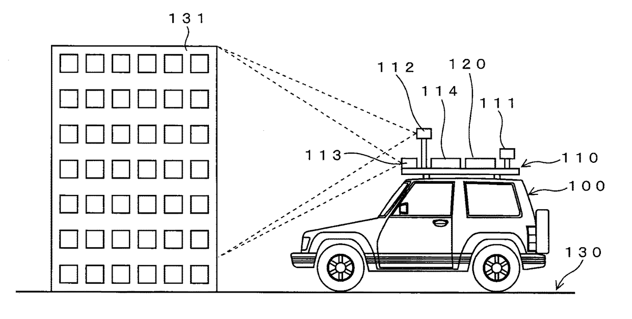
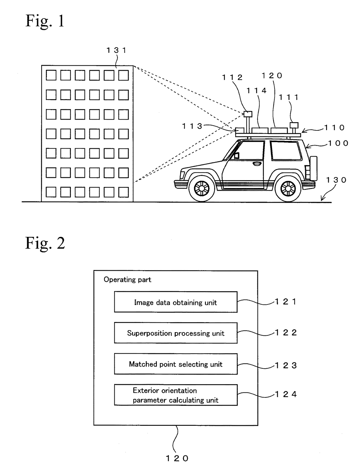
[0021]FIG. 1 shows a conceptual diagram of an embodiment. FIG. 1 shows a vehicle 100 mounted with a measuring system 110. The measuring system 110 has a base on which a GNSS unit 111, an operating part 120, a camera 112, a camera 113, and an IMU 114 are mounted.
[0022]The GNSS unit 111 receives navigation signals from a navigation satellite forming a GNSS (Global Navigation Satellite System) and outputs its location information and time information, which is calibrated and has high precision. The operating part 120 has a calculation function, described later.
[0023]The camera 112 is a reference camera, and it is fixed in a predetermined direction and photographs moving images. Naturally, the camera 112 can also photograph still images. The camera 112 is fixed to the vehicle 100 (IMU 114), and exterior orientation parameters thereof with respect to the vehicle 100 (IMU 114) are determined in advance. As the camera 112, a panoramic camera, which can photograp...
second embodiment
2. Second Embodiment
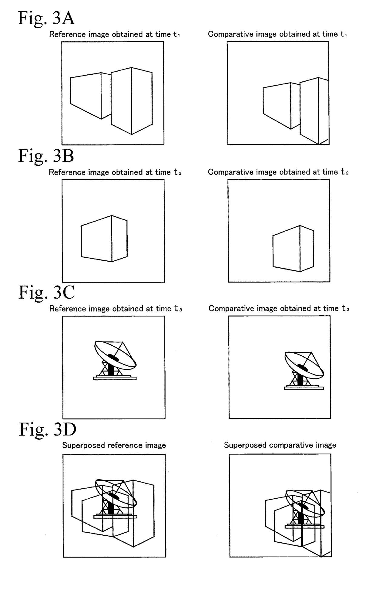
[0063]Another example of the processing performed by the superposition processing unit 122 will be described hereinafter. FIG. 6 shows an example of a procedure of a processing performed by the operating part 120. First, the vehicle 100 is started to travel in appropriate surroundings (for example, on the road surface 130) (see FIG. 1), and at the same time, objects, such as the building 131, are photographed by using the cameras 112 and 113 at multiple timings. This photographing is performed by synchronizing the cameras 112 and 113 so that the same objects appear in the photographed visual fields of the two cameras. In addition, the photographing should be performed so that different images are photographed at different timings. For example, moving images are photographed by synchronizing the two cameras, and image data of multiple synchronized frame images are obtained (Step S601).
[0064]FIGS. 7A to 7D show an example of a case of simultaneously performing phot...
third embodiment
3. Third Embodiment
[0069]In the First Embodiment or the Second Embodiment, if the position of the camera 113 with respect to the IMU 114 is known, but the attitude of the camera 113 is unknown, the exterior orientation parameter of the camera 113 with respect to the IMU 114 can be calculated in the same manner as in the case of the First Embodiment or the Second Embodiment.
4. Other Matters
[0070]There may be multiple cameras in which the exterior orientation parameters thereof are to be calculated. In this case, after the exterior orientation parameters of each camera are obtained, the errors may be distributed by bundle adjustment, whereby the precision of the calculated exterior orientation parameters can be increased.
[0071]Markers or targets may be used as the matched feature points. The distance between the cameras 112 and 113 may be determined by actual measurement. As a method for actually measuring the distance, a method of using, for example, laser light, the principle of tri...
PUM
 Abstract
Description
Claims
Application Information
 - R&D
- Intellectual Property
- Life Sciences
- Materials
- Tech Scout
- Unparalleled Data Quality
- Higher Quality Content
- 60% Fewer Hallucinations
Browse by: Latest US Patents, China's latest patents, Technical Efficacy Thesaurus, Application Domain, Technology Topic, Popular Technical Reports.
© 2025 PatSnap. All rights reserved.Legal|Privacy policy|Modern Slavery Act Transparency Statement|Sitemap|About US| Contact US: help@patsnap.com


