
Light microscopy chips and data analysis methodology for quantitative localized surface plasmon resonance (LSPR) biosensing and imaging

a technology of localized surface plasmon and data analysis, applied in the field of light microscopy chips and quantitative analysis methodology for localized surface plasmon resonance (lspr) biosensing and imaging, can solve the problems of convolution of solution-based changes, limited imagery, etc., and achieve the effect of convenient integration

Active Publication Date: 2018-03-13
THE UNITED STATES OF AMERICA AS REPRESENTED BY THE SECRETARY OF THE NAVY
View PDF2 Cites 2 Cited by
  • Summary
  • Abstract
  • Description
  • Claims
  • Application Information

AI Technical Summary

Benefits of technology

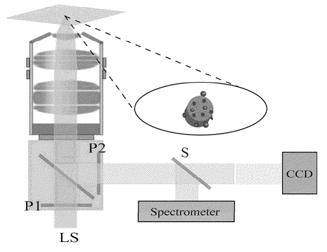
[0011]This application of LSPR biosensing and imaging has several advantages: (1) measurements are made in real-time, (2) the nanostructures are lithographically patterned onto standard glass coverslips enabling more traditional imaging techniques such as fluorescence and bright field imagery to be readily integrated, and (3) the nanostructures are calibrated for the quantitative determination of concentration as a function of time and space.

Problems solved by technology

First, because the spatial resolution of LSPR is restricted only by the size of the nanoparticle, the imagery is in principle diffraction limited and indeed spectroscopic-based biosensing with single nanostructures has already been achieved.
In addition, the fact that SPR is sensitive to dielectric variations hundreds of nanometers above the metallic surface can result in a convolution of solution- and surface-based changes.

Method used


Image

  • Light microscopy chips and data analysis methodology for quantitative localized surface plasmon resonance (LSPR) biosensing and imaging
  • Light microscopy chips and data analysis methodology for quantitative localized surface plasmon resonance (LSPR) biosensing and imaging
  • Light microscopy chips and data analysis methodology for quantitative localized surface plasmon resonance (LSPR) biosensing and imaging

Examples


Embodiment Construction

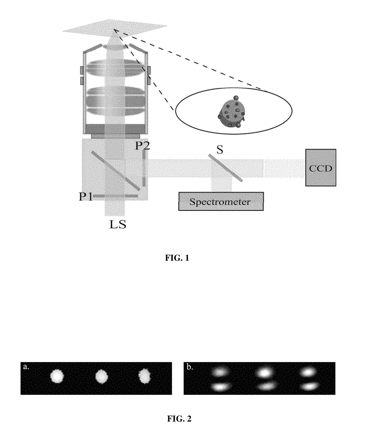
[0024]The present invention provides a methodology for the determination of the time-dependence of the surface-receptor fractional occupancy, f(t), based upon LSPR spectroscopic measurements using an array of functionalized gold plasmonic nanostructures. The nanostructures were patterned by electron-beam nanolithography (EBL) into 20×20 arrays and each array as a whole characterized spectroscopically in a reflected geometry on an inverted light microscope. The data analysis methodology of the present invention models the photon count in each spectrometer channel as the sum of a baseline scattering rate and a scattering term sensitive to the small dielectric perturbations due to the binding of biomolecules at the surface of the nanostructures. This non-linear least squares approach to the data analysis sums over hundreds of these channels, at each point in time, giving it a distinct statistical advantage over a single channel approach, such as monitoring the peak wavelength. In this ...


PUM

PropertyMeasurementUnit
sizeaaaaaaaaaa
diameteraaaaaaaaaa
diameteraaaaaaaaaa

Abstract

A chip for localized surface plasmon resonance (LSPR) biosensing and imaging having a glass coverslip compatible for use in a standard microscope and at least one array of functionalized plasmonic nanostructures patterned onto the glass coverslip with electron beam nanolithography. The nanostructures can be regenerated allowing the chip to be used multiple times. Also disclosed is a method for determining the fractional occupancy values for surface-bound receptors as a function of time for LSPR biosensing from the spectroscopic response of the array and modeling the photon count in each spectrometer channel, allowing for a functional relationship to be determined between the acquired spectrum and the fractional occupancy of binding sites on the array. Additionally disclosed is a method for the spatiotemporal mapping of receptor-ligand binding kinetics in LSPR imaging using the chip and projecting a magnified image of the array to a CCD camera and monitoring the binding kinetics of the array.

Description

PRIORITY CLAIM[0001]This Application claims priority from U.S. Provisional Application No. 61 / 706,911 filed on Sep. 28, 2012 by Marc P. Raphael et al., entitled “LIGHT MICROSCOPY AND DATA ANALYSIS METHODOLOGY FOR QUANTITATIVE LOCALZIED SURFACE PLASMON RESONANCE (LSPR) BIOSENSING AND IMAGING” and U.S. Provisional Application No. 61 / 839,428 filed on Jun. 26, 2013 by Marc P. Raphael et al., entitled “SILICON BACKING RING AND MULTIPLEXING APPLICATIONS FOR LSPR IMAGING.” The entire contents of each provisional application and all references cited throughout this application and the provisional applications are incorporated herein by reference.CROSS REFERENCE[0002]Cross reference is made to copending application Ser. No. 14 / 039,326, filed contemporaneously herewith, entitled “CALIBRATING SINGLE PLASMONIC NANOSTRUCTURES FOR QUANTITATIVE BIOSENSING,” by Marc P. Raphael, et al. the disclosure of which is incorporated herein by reference in its entirety.BACKGROUND OF THE INVENTION[0003]Field ...

Claims


Application Information

Patent Timeline
Patent Type & Authority Patents(United States)
IPC IPC(8): G01N33/551G01N21/552G01N33/543G01N33/557
CPCG01N33/557G01N21/554G01N33/54386G01N33/54373G01N33/54346
Inventor RAPHAEL, MARC P.CHRISTODOULIDES, JOSEPH A.BYERS, JEFF M.
Owner THE UNITED STATES OF AMERICA AS REPRESENTED BY THE SECRETARY OF THE NAVY
Learn More