
Geometry-based flight control system

a flight control and geometrie technology, applied in the field of geometrie-based flight control systems, can solve the problem of not being able to determine in advance every combination of actuators and associated parameters

Active Publication Date: 2018-03-06
KITTY HAWK CORP
View PDF3 Cites 26 Cited by
  • Summary
  • Abstract
  • Description
  • Claims
  • Application Information

AI Technical Summary

Benefits of technology

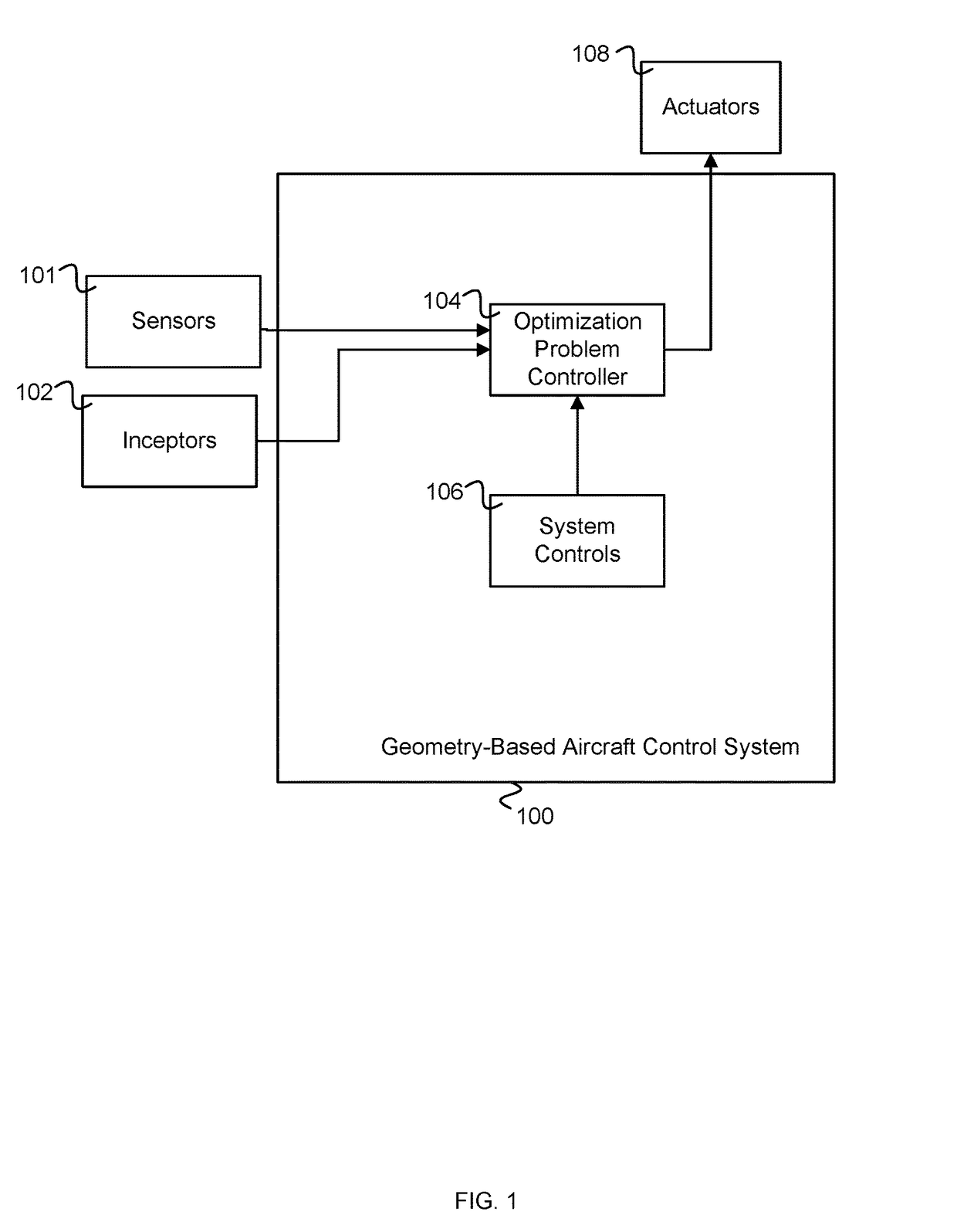
The invention is a geometry-based flight control system for aircraft that uses actuators to control the aircraft's movement. The system uses sensors and pilot controls to determine the position and direction of the aircraft and the desired motion. It uses pre-calculated combinations of actuators and parameters to respond to different pilot commands and situations. The system can be used in both fixed-wing and rotorcraft, and can be tailored to the specific aircraft design. The technical effect of the invention is to provide a more efficient and effective means of controlling the aircraft's movement and to improve safety and performance.

Problems solved by technology

However, typically it is not possible to determine in advance every combination of actuators and associated parameters that may be required under all possible conditions and circumstances.

Method used


Image

  • Geometry-based flight control system
  • Geometry-based flight control system
  • Geometry-based flight control system

Examples


Embodiment Construction

[0023]The invention can be implemented in numerous ways, including as a process; an apparatus; a system; a composition of matter; a computer program product embodied on a computer readable storage medium; and / or a processor, such as a processor configured to execute instructions stored on and / or provided by a memory coupled to the processor. In this specification, these implementations, or any other form that the invention may take, may be referred to as techniques. In general, the order of the steps of disclosed processes may be altered within the scope of the invention. Unless stated otherwise, a component such as a processor or a memory described as being configured to perform a task may be implemented as a general component that is temporarily configured to perform the task at a given time or a specific component that is manufactured to perform the task. As used herein, the term ‘processor’ refers to one or more devices, circuits, and / or processing cores configured to process da...


PUM


Abstract

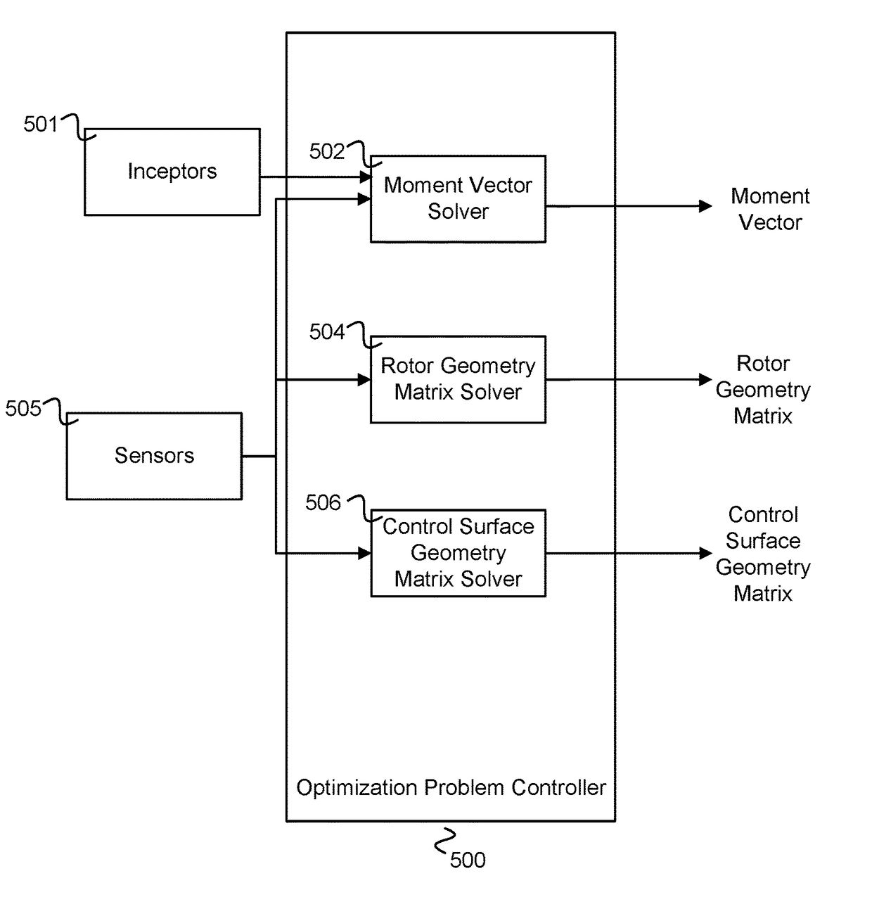
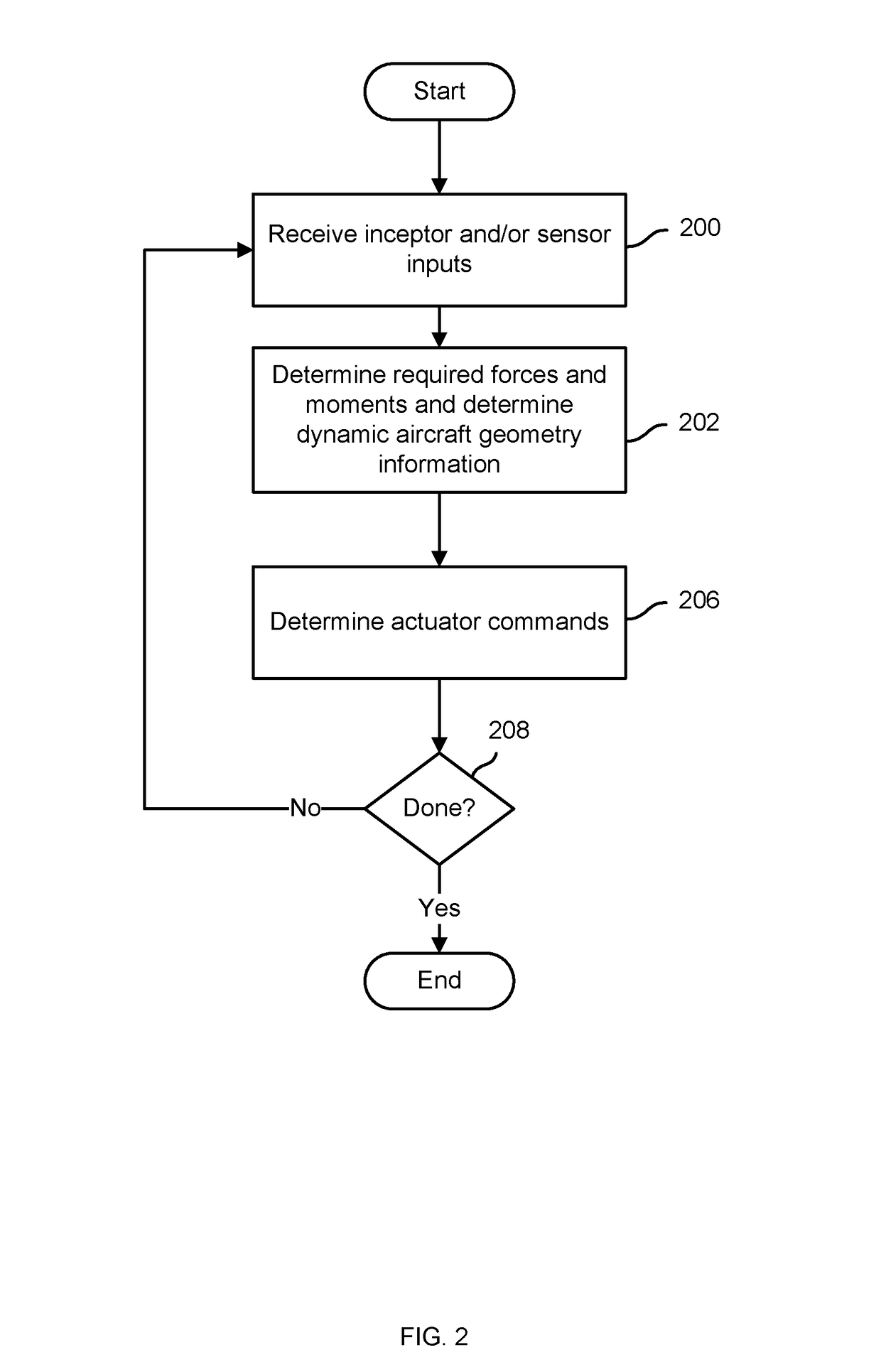
A geometry-based flight control system is disclosed. The geometry-based flight control system receives a set of inputs associated with a requested set of forces and moments to be applied to the aircraft and computes an optimal mix of actuators and associated actuator parameters to achieve to an extent practical the requested forces and moments. Computing the optimal mix of actuators and associated actuator parameters includes taking into consideration dynamically varying effectiveness of one or more actuators based on a dynamic state of the aircraft. For example, the dynamic state may comprise an angle of a tiltwing of the aircraft or an angle of a tilt rotor of the aircraft.

Description

BACKGROUND OF THE INVENTION[0001]Flight control systems (sometimes referred to as “flight controllers”) translate inputs received from manually operated pilot controls, such as one or more of a roll stick, rudder pedals, pitch stick, collective, and throttle controls, etc., referred to collectively herein as “inceptors”, and / or inputs from one or more sensors (e.g., air speed) into commands to the flight control assets of the aircraft, which may include one or more of control surfaces, such as rudders, ailerons, elevators, etc.; sources of forward thrust, such as propellers or jet engines; powered sources of lift such as rotors or lift fans; and forces capable of being directed or otherwise controlled or concentrated through use of nozzles, diverters, physical structures onto which engine or fan thrust may be directed, such as vanes, etc. and / or rotation of thrust generating devices.[0002]Each of the foregoing, and / or other equipment and structures, may be used to affect one or more...

Claims


Application Information

Patent Timeline
Patent Type & Authority Patents(United States)
IPC IPC(8): B64C27/08B64C15/12B64D31/06B64C13/18G05D1/08B64D45/00
CPCB64C13/18G05D1/0808B64D45/00B64D31/06B64C15/12B64D2045/0085B64C13/04B64C13/503B64C29/0033
Inventor HORN, GREGORY MAINLANDLIND, DAMON VANDER
Owner KITTY HAWK CORP
Learn More