Infrared apparatus

a technology of infrared apparatus and infrared light, which is applied in the field of infrared light apparatus, can solve the problems of increasing increasing the complexity of the structure of the assembly, and increasing so as to increase the cost of materials, and increase the number of assembling processes

Active Publication Date: 2018-02-27
DENSO CORP
View PDF13 Cites 0 Cited by
  • Summary
  • Abstract
  • Description
  • Claims
  • Application Information

AI Technical Summary

Benefits of technology

[0005]However, in the above case of the conventional structure, since the window part and the case are made of materials different from each other, the structure becomes complicated for assembling them to each other and the number of processes for the assembling also increases. Moreover, the visible light cut resin material is expensive, so the material cost also increases. Furthermore, when the case is made to have waterproof structure with protection against dust, it is necessary to arrange a gasket between the different materials or to integrally mold them, so the structure will become more complicated and the number of processes for the assembling will also increase.
[0006]The present disclosure is aimed to provide an infrared apparatus that can be easily assembled and that satisfies a conventional strength and light transmitting requirements.

Problems solved by technology

However, in the above case of the conventional structure, since the window part and the case are made of materials different from each other, the structure becomes complicated for assembling them to each other and the number of processes for the assembling also increases.
Moreover, the visible light cut resin material is expensive, so the material cost also increases.
Furthermore, when the case is made to have waterproof structure with protection against dust, it is necessary to arrange a gasket between the different materials or to integrally mold them, so the structure will become more complicated and the number of processes for the assembling will also increase.

Method used


Image

  • Infrared apparatus
  • Infrared apparatus
  • Infrared apparatus

Examples


Embodiment Construction

[0020]Hereafter, an infrared apparatus according to an embodiment of the present disclosure is described with reference to drawings.

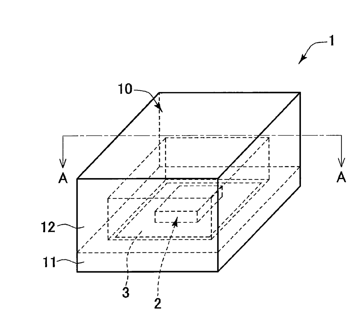
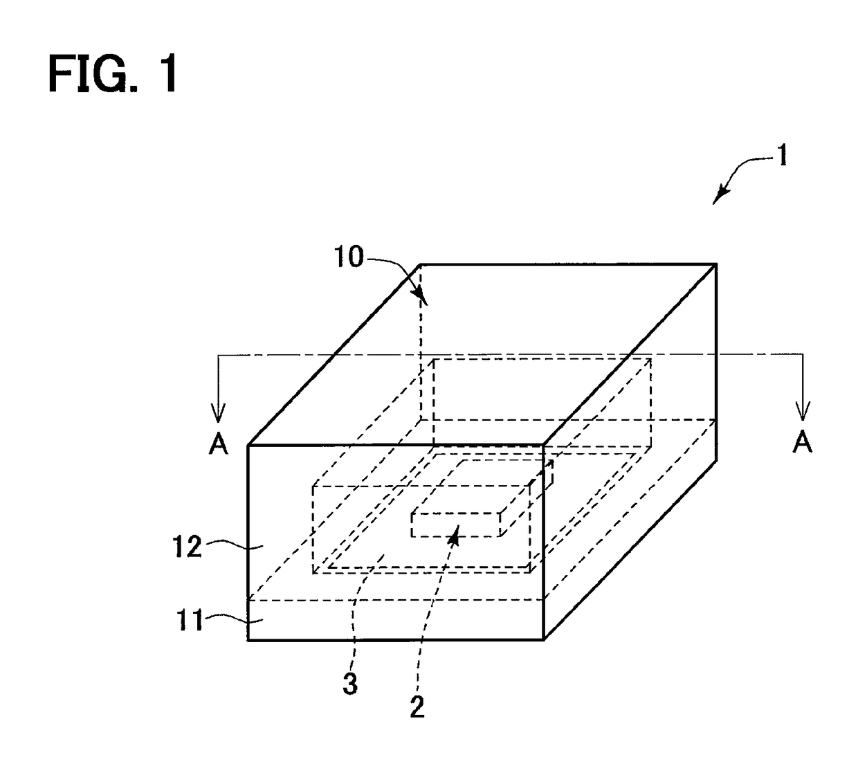
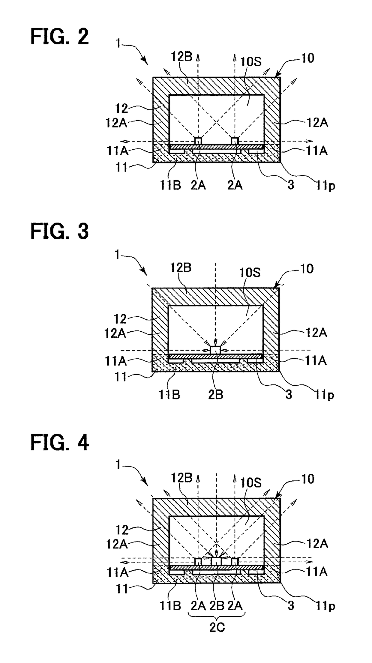
[0021]As shown in FIG. 1, an infrared apparatus 1 receives an infrared device 2 which inputs and / or outputs infrared rays in a case 10. The infrared device 2 is, for example, at least one of an infrared output device 2A, an infrared input device 2B, and an infrared output and input device 2C.

[0022]The case 10 has a case main part 11 and an infrared transmission window part 12 which does not transmit visible light and which transmits infrared light. The case main part 11 is a residual section except the infrared transmission window part 12, in the case 10. The infrared device 2 that is mounted on a circuit board 3 is disposed at the center on the upper surface of the case main part 11. The infrared transmission window part 12 covers the infrared device 2 and the circuit board 3 from the upper side, which are accommodated in the case interior space 10S, a...


PUM

PropertyMeasurementUnit
wavelengthaaaaaaaaaa

Abstract

An infrared apparatus includes a case, and an infrared device to input and / or output infrared rays. In the infrared apparatus in which the infrared device is received in the case, the case has an infrared transmitting window part which transmits only infrared light and which does not transmit visible light. Of a light transmitting resin through which near-infrared laser used for near-infrared laser welding passes and a light absorbing resin which emits heat and melts when receiving the near-infrared laser, the infrared transmitting window part is made of the light transmitting resin.

Description

CROSS REFERENCE TO RELATED APPLICATION[0001]This application is a U.S. national stage of International Application No. PCT / JP2013 / 006512 filed on Nov. 5, 2013 and is based on Japanese Patent Application No. 2012-259693 filed on Nov. 28, 2012, the disclosures of which are incorporated herein by reference.TECHNICAL FIELD[0002]The present disclosure relates to an infrared apparatus which inputs and / or outputs infrared rays.BACKGROUND ART[0003]An infrared apparatus has a case in which an infrared outputting device or infrared receiving device is arranged. The case has an infrared transmission window part through which only infrared light passes and visible light does not pass. Conventionally, visible light cut resin material is used for the window part, that is different from a case material met for mechanical requirement such as strength (for example, Patent Literature 1).PRIOR ART LITERATURESPatent Literature[0004]Patent Literature 1: JP 2001-103010 ASUMMARY OF INVENTION[0005]However,...

Claims


Application Information

Patent Timeline
Patent Type & Authority Patents(United States)
IPC IPC(8): G02B5/00B29C65/16B29C65/00B23K26/12B29L31/00B29L31/34
CPCG02B5/00B23K26/127B29C65/1616B29C65/1635B29C66/1142B29C66/542B29C66/733B29L2031/747B29C65/1677B29C66/71B29C66/73115B29C66/73321B29C66/73921B29C66/8322B29K2995/0027B29L2031/3481B29K2067/006
Inventor ISHIKAWA, RYUSUKEKOYAMA, YONOSUKEHATANO, MAKOTOKAWASHIMA, SEIZABUROU
Owner DENSO CORP
Why Eureka
Try Eureka