Cover, electronic device therewith and method for manufacturing the same
a technology of electronic devices and covers, which is applied in the direction of manufacturing tools, casings/cabinets/drawer details, instruments, etc., can solve the problems of limiting the development of mobile phones with glass components, unreasonable failures, and constraining the implementation flexibility of glass components, so as to improve the implementation flexibility of mobile phones
- Summary
- Abstract
- Description
- Claims
- Application Information
AI Technical Summary
Benefits of technology
Problems solved by technology
Method used
Image
Examples
first embodiment
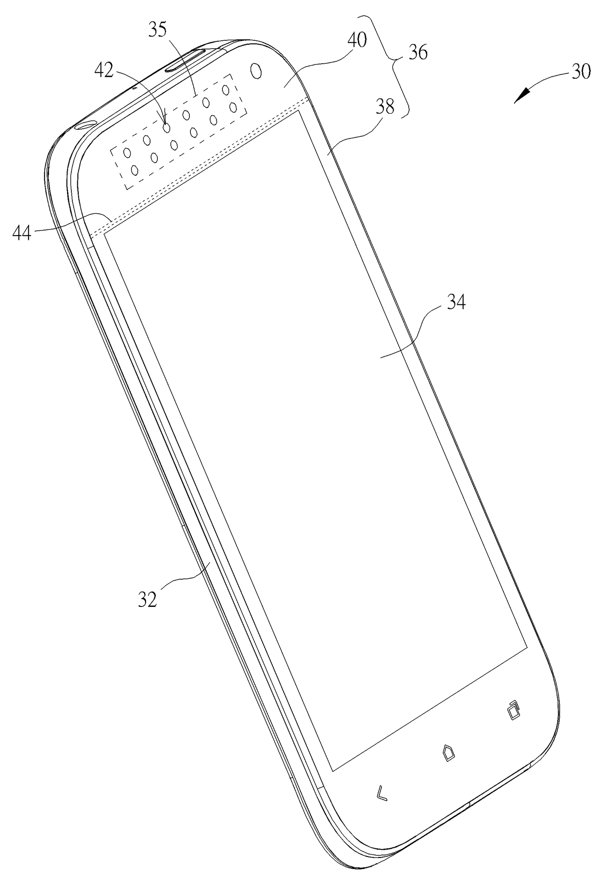
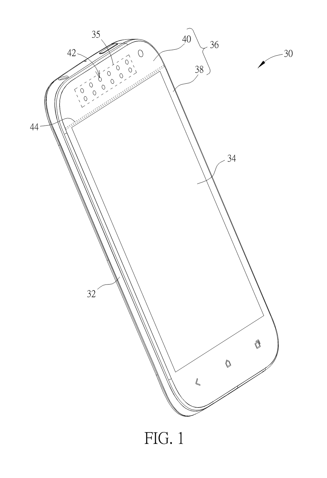
[0021]Please refer to FIG. 1. FIG. 1 is a schematic diagram of an electronic device 30 according to the present disclosure. In this embodiment, the electronic device 30 is a mobile phone, and implementation of the electronic device 30 is not limited to those mentioned in this embodiment. For example, the electronic device 30 can be a portable electronic device, such as a tablet computer, a notebook computer and so on. As for which one of the aforesaid designs is adopted, it depends on practical demands.
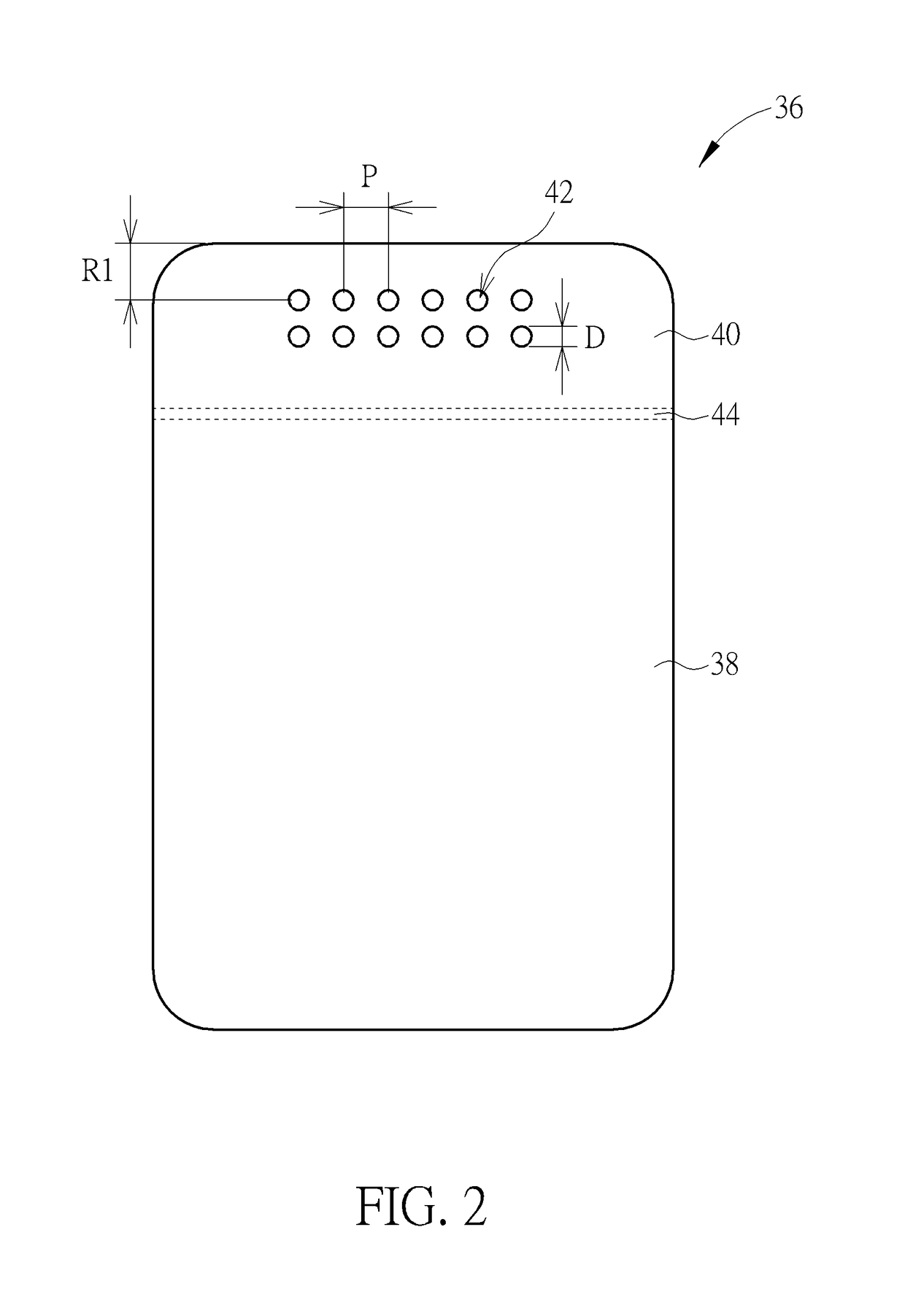
[0022]As shown in FIG. 1, the electronic device 30 includes a casing 32, a panel module 34 and at least one electronic component 35. The casing 32 is used for containing inner components of the electronic device 30, so as to prevent the inner components from damages due to collision. The panel module 34 is installed within the casing 32, and the at least one electronic component 35 is disposed within the casing 32. In this embodiment, the panel module 34 is, but not limited to, a touc...
second embodiment
[0040]Please refer to FIG. 5. FIG. 5 is a diagram of a cover 136 according to the present disclosure. As shown in FIG. 5, the main difference between the cover 136 and the aforesaid cover 36 is that at least one fine feature 142 of the cover 136 includes a slot, wherein a length L of the slot is smaller than 20 mm, a width W of the slot is approximately between 0.5 mm and 1.0 mm, and a distance R2 between an edge of the second covering member 40 and the slot is greater than 2 mm. Components with denoted in this embodiment identical to those in the aforesaid embodiment have identical structures and functions, and further description is omitted herein for simplicity.
third embodiment
[0041]Please refer to FIG. 6. FIG. 6 is a diagram of a cover 236 according to the present disclosure. As shown in FIG. 6, the main difference between the cover 236 and the aforesaid cover 36 is that the cover 236 includes four fine features 242 wherein four second covering members 40 are connected between the four fine features 242 and four edges of the first covering member 38, respectively. In this embodiment, the four fine features 242 are respectively a curved structure. In other words, since the second covering member 40 can be made of plastic material, the fine feature 242 on the second covering member 40 can be created in a curved shape in plastic molding manner, so that the cover 236 can be made as a curved glass part. Components with denoted in this embodiment identical to those in the aforesaid embodiment have identical structures and functions, and further description is omitted herein for simplicity.
[0042]It should be noticed that structures of the fine feature are not l...
PUM
| Property | Measurement | Unit |
|---|---|---|
| thicknesses | aaaaa | aaaaa |
| diameter | aaaaa | aaaaa |
| diameter | aaaaa | aaaaa |
Abstract
Description
Claims
Application Information
 - R&D
- Intellectual Property
- Life Sciences
- Materials
- Tech Scout
- Unparalleled Data Quality
- Higher Quality Content
- 60% Fewer Hallucinations
Browse by: Latest US Patents, China's latest patents, Technical Efficacy Thesaurus, Application Domain, Technology Topic, Popular Technical Reports.
© 2025 PatSnap. All rights reserved.Legal|Privacy policy|Modern Slavery Act Transparency Statement|Sitemap|About US| Contact US: help@patsnap.com


