Top drive operated casing running tool

a top drive and casing technology, applied in the field of tools, can solve problems such as stress cracks in the casing, and achieve the effect of facilitating extension or retraction of slips and facilitating insertion

Active Publication Date: 2018-02-20
MCCOY GLOBAL
View PDF18 Cites 7 Cited by
  • Summary
  • Abstract
  • Description
  • Claims
  • Application Information

AI Technical Summary

Benefits of technology

[0008]In an alternative embodiment, spring loaded dogs can be attached to the housing to engage the casing internally or externally to facilitate extension or retraction of the slips that selectively grab the topmost of a string of casing. When the tool is suspended from the top drive, its components are rotationally locked to facilitate insertion into the casing stand on top of a string being run in the hole. Some set down weight allows top drive rotation to move a multi-ramped mandrel axially because that mandrel is rotationally locked to the housing that is held fast by the spring loaded dogs bearing on the casing. Once the slips are extended with a specified torque applied from the top drive, further setting down weight locks the components and the housing so that applied rotation with setting down weight will turn the casing string but will not torque up the slips beyond their set position which could cause stress cracks to the casing. A return spring returns the components to a rotationally locked position with respect to the housing so the process can be repeated after the slips get retracted with rotation in an intermediate position between hanging and weight fully set down. Components can be rotationally locked when driving in the string into the borehole with backpressure from circulating fluid employed to hold the components in a rotationally locked relation so that the string can be manipulated as it is inserted without slip radial movement in opposed directions.

Problems solved by technology

Once the slips are extended with a specified torque applied from the top drive, further setting down weight locks the components and the housing so that applied rotation with setting down weight will turn the casing string but will not torque up the slips beyond their set position which could cause stress cracks to the casing.

Method used


Image

  • Top drive operated casing running tool
  • Top drive operated casing running tool
  • Top drive operated casing running tool

Examples


Embodiment Construction

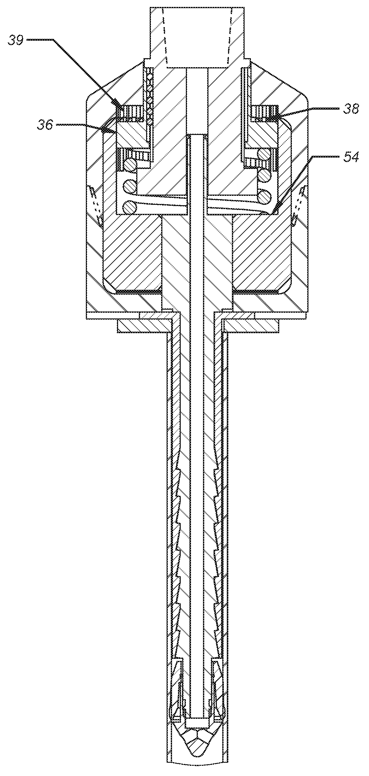
[0021]Referring to FIG. 1 a top drive TD is schematically illustrated as supporting a top sub 3 at threads 30. The top sub 3 is rotationally locked to driving nut 1 that is captured above shoulder 32 leaving an exposed annular surface 34 on which spring 5 exerts and upward force. Driving nut 1 is rotationally locked to top sub 3 with locking balls 9 although other ways to rotationally lock can be used. Drive nut 1 has an exterior gear pattern or splines 36 that in the FIG. 1 position are engaged with an internal gear or splines 38 on driven nut 2 and with splines 39 on an interior wall of the housing 7 when subjected to the force of spring 5. Splines 39 are best seen in FIG. 8 when the driving gear 1 is pushed down to expose splines 39. Driven nut 2 is mounted to rotate in housing components 6 and 7. Driven nut 2 is connected to actuator 10 at thread 40 such that rotation of the driven nut 2 by driving nut 1 through meshed splines 36 and 38 result in axial translation of actuator 10...


PUM


Abstract

Spring loaded dogs are attached to the housing to engage the casing internally or externally to facilitate extension or retraction of the slips that selectively grab the topmost of a string of casing. When the tool is suspended from the top drive, its components are rotationally locked to facilitate insertion into the casing stand on top of a string being run in the hole. Some set down weight allows top drive rotation to move a multi-ramped mandrel axially because that mandrel is rotationally locked to the housing that is held fast by the spring loaded dogs bearing on the casing. Once the slips are extended with a specified torque applied from the top drive, further setting down weight locks the components and the housing so that applied rotation with setting down weight will turn the casing string but will not torque up the slips beyond their set position.

Description

CROSS REFERENCE TO RELATED APPLICATION[0001]This application is a continuation-in-part of U.S. patent application Ser. No. 14 / 056,362, for “Top Drive Operated Casing Running Tool”, filed on Oct. 17, 2013, and claims the benefit of priority from the aforementioned application.FIELD OF THE INVENTION[0002]The field of the invention is tools that assemble and deliver tubular strings into a borehole and more particularly top drive driven tools that allow circulation, makeup and movement of the string as it is assembled into the borehole.BACKGROUND OF THE INVENTION[0003]In the past manipulation, threading and circulation of casing or tubulars was done with a variety of tools such as fill up and circulation tools that featured a seal to the inside or the outside of the tubular to be able to pump fluid as the tubular string was lowered into the borehole or to initially fill that last segment that was added to the string before running in. Typically the handling of a joint to be added to a s...

Claims


Application Information

Patent Timeline
Patent Type & Authority Patents(United States)
IPC IPC(8): E21B19/07E21B19/00E21B19/06
CPCE21B19/07E21B19/06E21B19/00
Inventor MULLINS, ALBERT AUGUSTUSHICKL, MATTHEW J.
Owner MCCOY GLOBAL
Why Eureka
Try Eureka