Pneumatic tire with rectangle-sheet-shaped carcass ply pieces

a pneumatic tire and rectangle-sheet technology, applied in the field of pneumatic tires, can solve the problems of obvious expression of poor appearance, and achieve the effect of reducing the generation of poor appearance and reducing the partial increase of cord density

Active Publication Date: 2018-02-13
SUMITOMO RUBBER IND LTD
View PDF13 Cites 0 Cited by
  • Summary
  • Abstract
  • Description
  • Claims
  • Application Information

AI Technical Summary

Benefits of technology

[0014]The pneumatic tire of the present invention comprises the carcass formed of at least a single carcass ply extending from the tread portion through the sidewall portion to the bead portion. The carcass ply is made by arranging the rectangle-sheet shaped ply pieces in the circumferential direction of the tire. In each of the ply pieces, a radial length is larger than a circumferential length.
[0015]Each of the ply pieces has parallelly-arranged carcass cords along the longitudinal direction. And the ply piece is overlapped on the circumferentially adjacent ply pieces at least partially. Therefore, the carcass ply can absorb the difference between the circumferential lengths on the tread portion side and the bead portion side. The pneumatic tire of the present invention is therefore capable of reducing the generation of a wrinkle of the carcass ply and forming the carcass ply into a toroidal shape.
[0016]Moreover, in each of the ply pieces, the carcass cords in at least one of side edge portions, in the circumferential direction, of the ply piece have a spacing Pe larger than a spacing Pc of the carcass cords in a central portion of the ply piece. This can reduce the partial increase of cord density caused by overlap of the ply pieces in the carcass ply. Therefore, the pneumatic tire of the present invention is capable of reducing the generation of the poor appearance such as the dent (dint).BRIEF EXPLANATION OF THE DRAWING
[0017]FIG. 1 is a diagrammatic perspective view showing a pneumatic tire forming the present embodiment.
[0018]FIG. 2 is a diagrammatic perspective view showing an inner mold of carcass plies.
[0019]FIG. 3 is a diagrammatic perspective view showing a ply piece.

Problems solved by technology

Specifically, the poor appearance was liable to be obviously expressed in the sidewall portion 3 having a small rubber volume.

Method used


Image

  • Pneumatic tire with rectangle-sheet-shaped carcass ply pieces
  • Pneumatic tire with rectangle-sheet-shaped carcass ply pieces
  • Pneumatic tire with rectangle-sheet-shaped carcass ply pieces

Examples


example

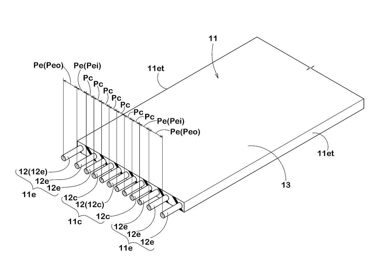
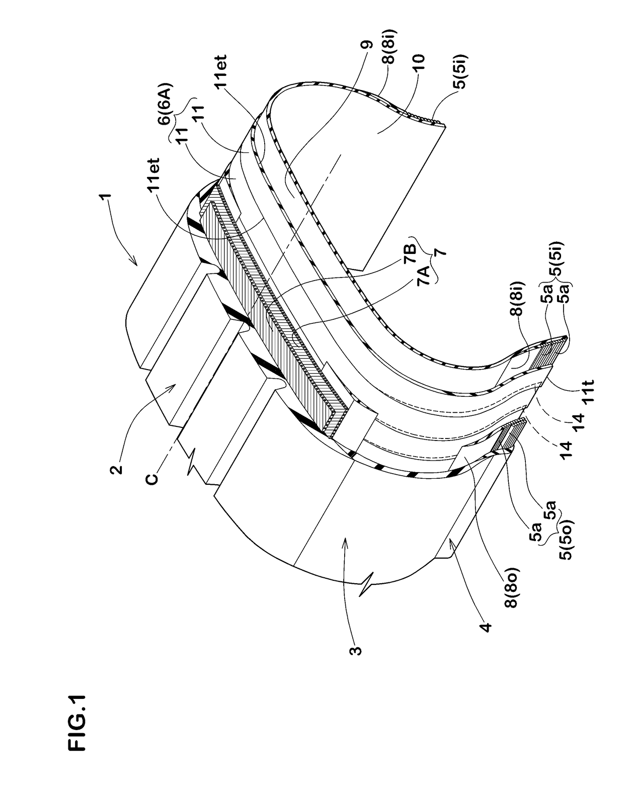
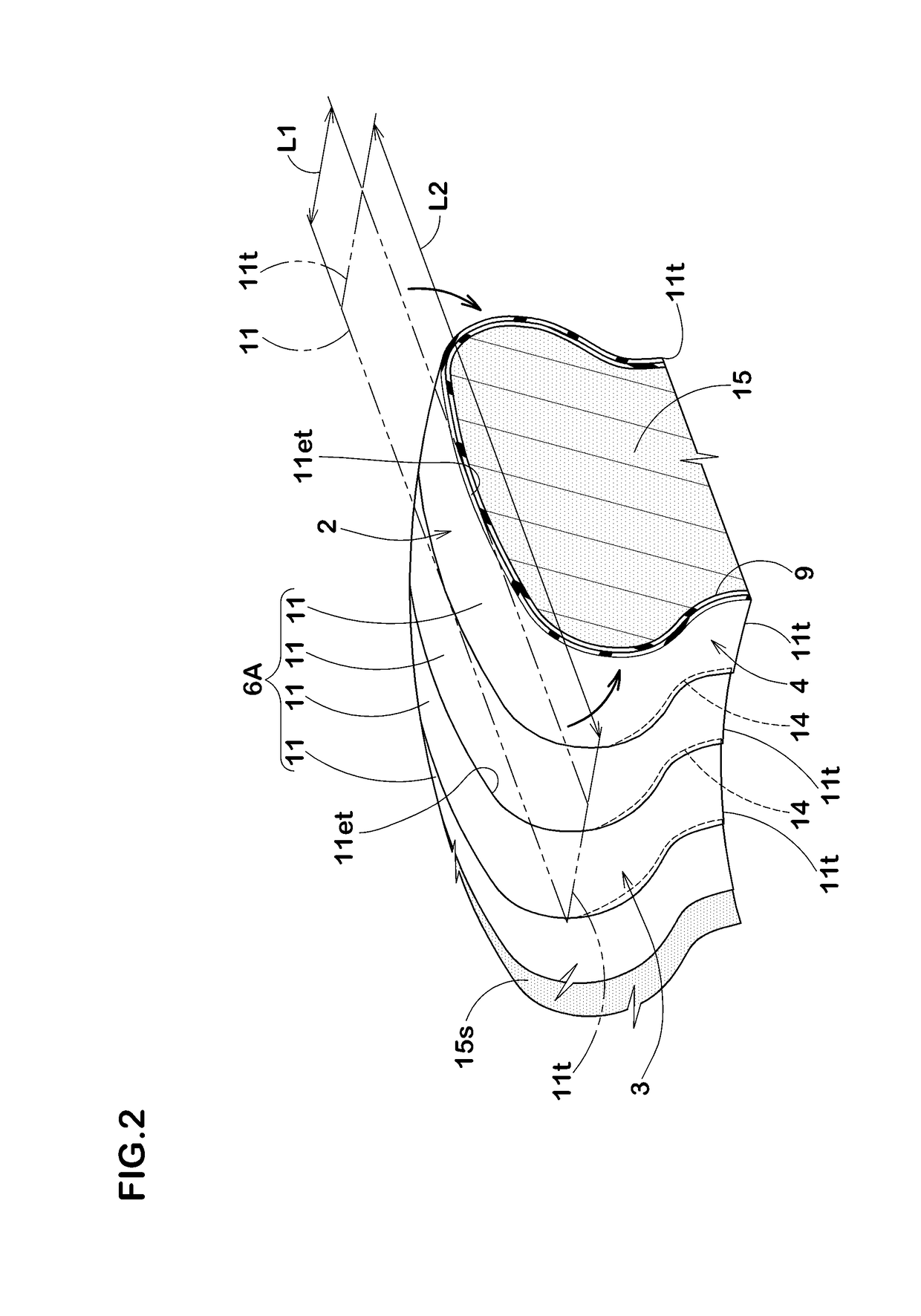
[0055]A test tire having a basic structure as shown in FIG. 1 and comprising a ply pieces shown in Table 1 was manufactured and tested performances. For comparison, a conventional tire (Comparative Example) comprising a ply pieces having an even spacing (P=1.3 mm) of the carcass cord shown in FIG. 5 was tested in the same way. The common specifications were as follows:

[0056]Tire size: 195 / 65R15

[0057]Rim size: 15×6 J

[0058]Thickness of sidewall portion: 1.5 mm

[0059]Ply piece:[0060]Circumferential length L1: 28 mm

[0061]Carcass cord:[0062]Cord material: polyester[0063]Structure of cord: 1670 / 2 dtex

The test method was as follows:

[0064]

[0065]The test tire was mounted on the rim, and inflated an internal pressure to 300 kP. Then, visually confirm the presence or absence of poor appearance such as a dent from a sidewall portion to a bead portion. Evaluation was performed in an appearance of the tire and displayed on a score of one to ten. The larger the score, the better appearance is. More...


PUM

PropertyMeasurementUnit
angleaaaaaaaaaa
angleaaaaaaaaaa
circumferential length L1aaaaaaaaaa

Abstract

A pneumatic tire is provided with a carcass configured from at least one carcass ply. The carcass ply is formed by arranging, in the tire circumferential direction, rectangular sheet-shaped ply pieces, each having a radial direction length larger than a tire circumferential direction length. In each of the ply pieces, carcass cords are arranged parallel to each other in the longitudinal direction, and adjacent ply pieces at least partially overlap with each other in the tire circumferential direction, and in each of the ply pieces, the distance (Pe) between the carcass cords in at least one side edge portion in the circumferential direction of the ply piece, is larger than the distance (Pc) between the carcass cords in a central portion of the ply piece.

Description

TECHNICAL FIELD[0001]The present invention relates to a pneumatic tire capable of reducing generation of poor appearance.BACKGROUND ART[0002]In FIGS. 2 and 5, there is proposed a method for manufacturing a pneumatic tire to form a toroidal carcass ply 6A by use of an inner mold 15 having rigidity (see the under-mentioned Patent Document 1, for example). In this manufacturing method, the toroidal carcass ply 6A is formed by adhering rectangle-sheet shaped ply pieces 11 on an outer surface 15s of the inner mold 15 via inner liner rubber 9, for example.[0003]Each of the ply pieces 11 has a radial length L2 longer than a circumferential length L1. As shown in FIG. 5, the each of the ply pieces 11 has parallelly-arranged carcass cords 12 along the longitudinal direction. In the circumferential direction, the ply piece 11 has a spacing P of the carcass cords 12 is equal.[0004]Such a method for manufacturing is more capable of reducing circumferential unevenness of the spacing P of carcass...

Claims


Application Information

Patent Timeline
Patent Type & Authority Patents(United States)
IPC IPC(8): B60C9/04B60C5/00B60C9/02B29D30/38B29D30/42
CPCB60C9/04B60C5/00B60C9/023B29D30/38Y10T152/10855B29D2030/423B60C2009/0408B60C2009/0441B29D30/42
Inventor SUGIYAMA, NAOKI
Owner SUMITOMO RUBBER IND LTD
Why Eureka
Try Eureka