Non-linear precoder with separate tracking

a precoder and non-linear technology, applied in the field of crosstalk mitigation within a wired communication system, can solve the problems of limited vectoring gain, severe signal distortion, unfair distribution of bit rate to different users, etc., and achieve the effect of reducing complexity

Active Publication Date: 2018-02-06
ALCATEL LUCENT SAS
View PDF10 Cites 1 Cited by
  • Summary
  • Abstract
  • Description
  • Claims
  • Application Information

AI Technical Summary

Benefits of technology

[0058]In one embodiment of the invention, the controller is further configured to lower initial direct channel gains for the respective communication channels by a given margin with respect to respective transmit power masks.
[0068]The present invention proposes to insert pilot signals at different locations in the transceiver chain, to measure the corresponding residual crosstalk in order to obtain estimates of different concatenations of channels, and next to apply this information for updating one of the precoder blocks in a low-complex manner. The remaining precoder blocks are left unchanged, and are updated only when a certain threshold is reached. The fewer update of the remaining blocks reduces the complexity, as well as the amount of overhead signaling with the far-end receivers.

Problems solved by technology

Crosstalk (or inter-channel interference) is a major source of channel impairment for Multiple Input Multiple Output (MIMO) wired communication systems, such as Digital Subscriber Line (DSL) communication systems.
Yet, local loop unbundling on account of national regulation policies and / or limited vectoring capabilities may prevent such an exhaustive approach, in which case the vectoring group would include a sub-set only of all the physically interacting lines, thereby yielding limited vectoring gains.
The superimposition of the crosstalk precompensation signals on the victim line may thus cause a violation of the transmit Power Spectral Density (PSD) mask, which defines the allowed amount of signal power for an individual user as a function of frequency, and may as well result in signal clipping within the Digital to Analog Converter (DAC) causing severe signal distortions.
Yet, modulo operation directly affects the transmit signal and thus the actual crosstalk induced onto the system, ending into a ‘chicken-egg’ problem: modulo operation for a first user alters precompensation for a second user; altered precompensation for the second user alters modulo operation for the second user; altered modulo operation for the second user user alters precompensation for the first user; and altered precompensation for the first user alters modulo operation for the first user; and so on.
We also note that for a cable with identical lines, the diagonal values of the R* matrix do not have the same value; hence the noise enhancement is not the same on each line, which may lead to an unfair distribution of bit rates to the different users depending on the level of crosstalk couplings.
A major issue with non-linear precoding is the amount of processing resources required for updating the non-linear precoder.
Another issue is that the non-linear precoder breaks the orthogonality of the pilot sequence, thereby biasing in the crosstalk estimates.
To overcome this issue, one can either reduce the transmit power of the pilot (leading to slower convergence), or treat the modulo-pilots as quasi-orthogonal (leading to slower convergence, if any), or to not apply modulo operation (leading to PSD mask violation and clipping).
None of these solutions are satisfactory.

Method used


Image

  • Non-linear precoder with separate tracking
  • Non-linear precoder with separate tracking
  • Non-linear precoder with separate tracking

Examples


Embodiment Construction

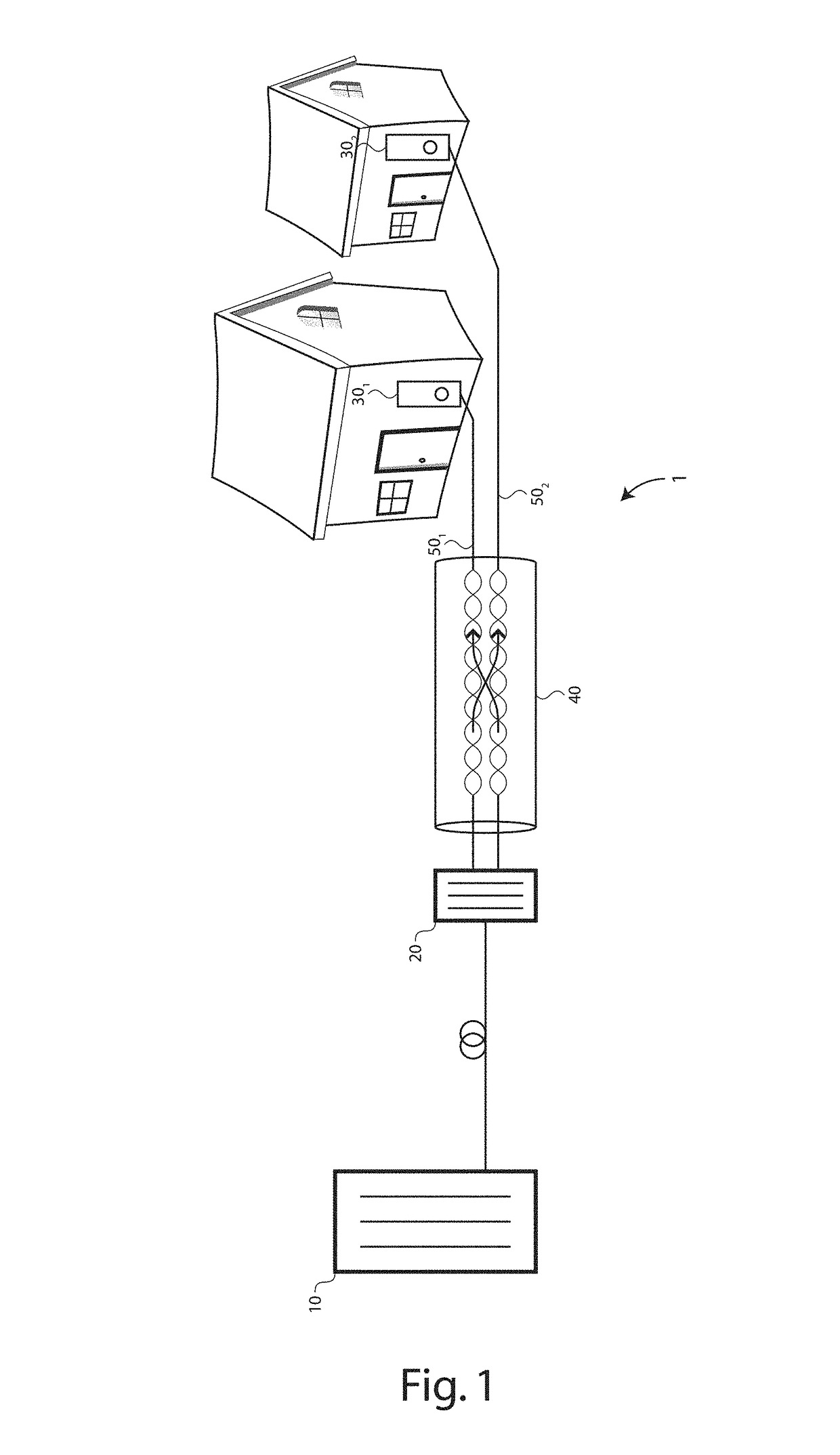
[0077]There is seen in FIG. 1 an access plant 1 comprising a network unit 10 at a CO, a DPU 20 coupled via one or more optical fibers to the network unit 10, and further coupled via a copper loop plant to Customer Premises Equipment (CPE) 30 at various subscriber premises.

[0078]The copper loop plant comprises a common access segment 40, wherein the subscriber lines are in close vicinity with each other and thus induce crosstalk into each other, and dedicated loop segments 50 for final connection to the subscriber premises. The transmission media is typically composed of copper Unshielded Twisted Pairs (UTP).

[0079]The DPU 20 comprises a vectoring processing unit for jointly processing the data symbols that are being transmitted over, or received from, the loop plant in order to mitigate the crosstalk induced within the common access segment and to increase the communication data rates achievable over the respective subscriber lines.

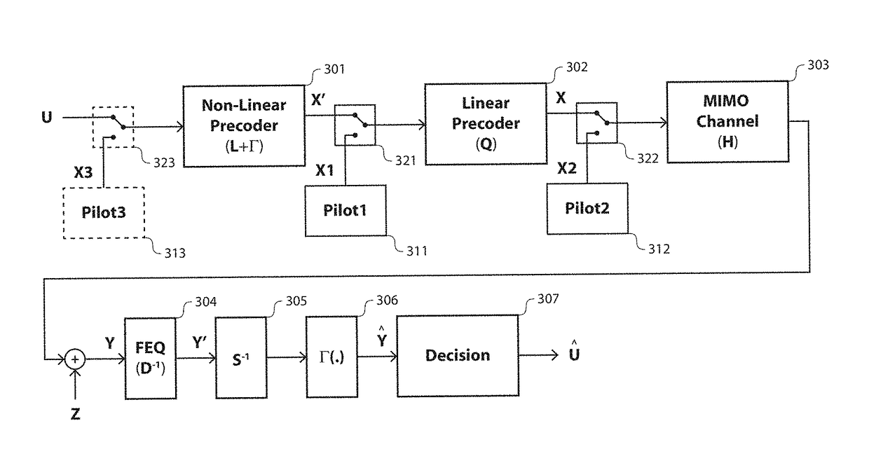
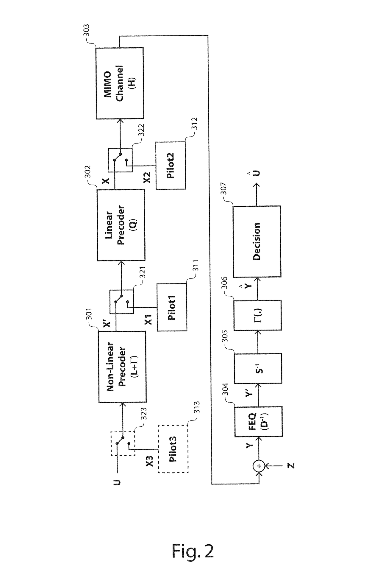
[0080]There is seen in FIG. 2 a conceptual represent...


PUM


Abstract

A network unit includes a non-linear precoder for jointly pre-processing transmit samples to be transmitted over respective communication channels for crosstalk mitigation. The non-linear precoder includes a first non-linear precoding stage configured to operate according to a first triangular precoding matrix and including a modulo function, followed by a second linear precoding stage configured to operate according to a second precoding matrix. The network unit further includes a first pilot signal generator configured to generate first pilot signals for pre-processing by the second precoding stage only to yield partially-precoded pilot signals for further transmission over the respective communication channels, and a controller configured to update the second precoding matrix based on first error measurements performed during the transmission of the partially-precoded pilot signals over the respective communication channels while keeping the first precoding matrix unaltered.

Description

CROSS-REFERENCE TO RELATED APPLICATIONS[0001]This application is a national phase under 35 U.S.C. §371 of PCT International Application No. PCT / EP2015 / 054809 which has an International filing date of Mar. 9, 2015, which claims priority to European Application No. 14305349.4, filed Mar. 11, 2014, the entire contents of each of which are hereby incorporated by reference.TECHNICAL FIELD OF THE INVENTION[0002]The present invention relates to crosstalk mitigation within a wired communication system.TECHNICAL BACKGROUND OF THE INVENTION[0003]Crosstalk (or inter-channel interference) is a major source of channel impairment for Multiple Input Multiple Output (MIMO) wired communication systems, such as Digital Subscriber Line (DSL) communication systems.[0004]As the demand for higher data rates increases, DSL systems are evolving toward higher frequency bands, wherein crosstalk between neighboring transmission lines (that is to say transmission lines that are in close vicinity over part or w...

Claims


Application Information

Patent Timeline
Patent Type & Authority Patents(United States)
IPC IPC(8): H04B7/02H04B3/32H04L25/03H04L5/14H04L5/00H04B7/04H04L1/00H04L25/02H04L25/497H04B7/0413H03M13/35
CPCH04B3/32H04B7/0465H04L1/0011H04L1/0033H04L5/0048H04L25/0204H04L25/0226H04L25/03343H04L5/143H04L25/4975H03M13/353H04B7/0413
Inventor MAES, JOCHENTIMMERS, MICHAEL
Owner ALCATEL LUCENT SAS
Why Eureka
Try Eureka